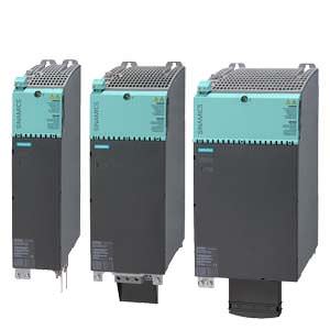
Basic Line Modules in booksize format Siemens
Обзор
Basic Line Modules in booksize format
Basic Line Modules are used for applications in which no energy is returned to the supply or where the energy exchange between motor and generator axes takes place in the DC link. Basic Line Modules can only feed energy from the supply system into the DC link, energy cannot be fed back into the supply system. The DC link voltage is directly derived from the 3‑phase line voltage via a 6‑pulse bridge circuit. Basic Line Modules are designed for connection to grounded, star TN/TT systems and non-grounded, symmetrical IT systems. The connected Motor Modules are pre-charged over the integrated pre-charging resistors (20 kW and 40 kW) or through activation of the thyristors (100 kW).
The 20 kW and 40 kW Basic Line Modules are equipped with an integrated brake chopper. With the addition of an external braking resistor, they can be used for applications with intermittent regenerative operation such as stopping. A Braking Module is required with a 100 kW Basic Line Module in addition to an external braking resistor for regenerative operation.
Дизайн
The Basic Line Modules in booksize format feature the following connections and interfaces as standard:
- 1 power connection
- 1 connection for the 24 V DC electronics power supply
- 1 DC link connection
- 3 DRIVE‑CLiQ sockets
- 1 connection for braking resistor
(20 kW and 40 kW Basic Line Modules only) - 1 temperature sensor input
The status of the Basic Line Modules is indicated via two multi-color LEDs.
The scope of supply of the Basic Line Modules includes:
- DRIVE‑CLiQ cable for connection to the adjacent Control Unit on the left for drive control, length 0.11 m (4.33 in)
- DRIVE‑CLiQ cable (length depends on module width) to connect Basic Line Module to adjacent Motor Module, length = width of Basic Line Module + 0.11 m (4.33 in)
- Jumper for connecting the 24 V DC busbar to the adjacent Motor Module
- 24 V terminal adapter (X24)
- Connector X21
- 2 blanking plugs for sealing unused DRIVE‑CLiQ sockets
- 1 set of warning signs in 30 languages
- 1 heat conducting foil
(for Basic Line Modules with cold platecooling only)
Характеристика
Overload capability
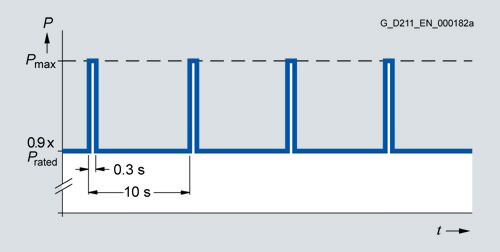
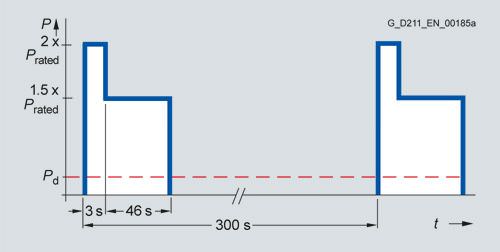
Load cycle with previous load
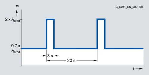
Load cycle with previous load
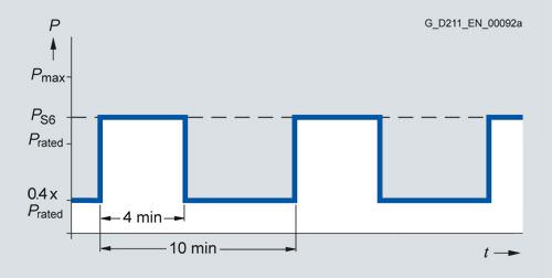
S6 load cycle with previous load
20 kW (26.8 HP) and 40 kW (53.6 HP) Basic Line Modules only
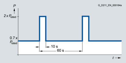
Load cycle with previous load
Derating characteristics
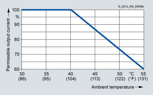
Output power dependent on ambient temperature
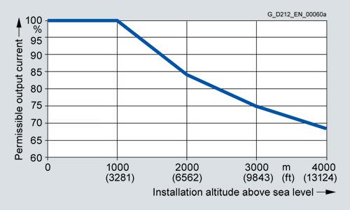
Output power dependent on installation altitude
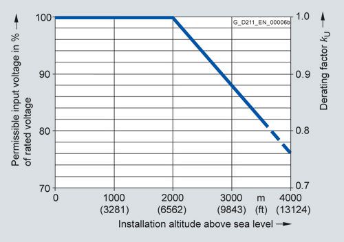
Voltage derating dependent on installation altitude
Braking power with external brake resistance
The following load cycles are defined for the braking modules of the 20 kW and 40 kW Basic Line Modules:
The maximum possible braking power Pmax is calculated using the following formula:
Pmax = U2/R
U = Activation threshold
R = Resistance value of the external braking resistor
The maximum braking power is achieved with the smallest permissible resistance value. The maximum possible braking power falls at larger resistance values.
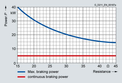
Braking power of the 20 kW Basic Line Modules depending on the connected braking resistor
When the recommended braking resistor is used, the following values result for the maximum braking power or continuous braking power:
Braking resistor 6SE7023‑2ES87‑2DC0
Resistance value = 20 Ω → max. braking power = 30 kW;
continuous braking power = 5 kW
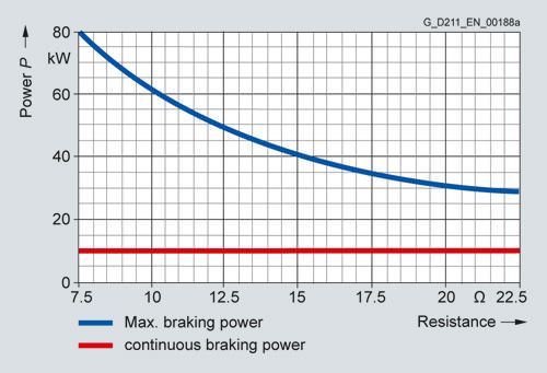
Braking power of the 40 kW Basic Line Modules depending on the connected braking resistor
When the recommended braking resistor is used, the following values result for the maximum braking power or continuous braking power:
Braking resistor 6SE7028‑0ES87‑2DC0
Resistance value = 8 Ω → max. braking power = 75 kW;
continuous braking power = 10 kW (limited by braking module)
Интеграция
The Basic Line Module communicates with a CU320‑2 or SIMOTION D4x5 2 Control Unit or Controller Extension CX32‑2 via DRIVE‑CLiQ.
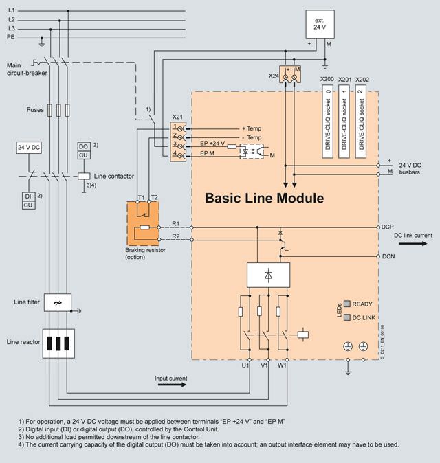
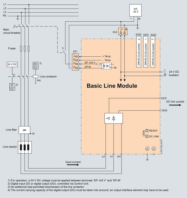
Connection example for 20 kW and 40 kW Basic Line Modules in booksize format
Note: The thermostatic switch built into the braking resistor must be looped into the shutdown chain of the drive to prevent thermal overloading of the system in the event of a fault. If a braking resistor is not connected, a jumper must be connected between X21.1 and X21.2.
Connection example for 100 kW Basic Line Module in booksize format
Технические данные
Basic Line Modules in booksize format 6SL313... |
|
|---|---|
Line connection voltage (up to 2000 m (6562 ft) above sea level) | 380 ... 480 V 3 AC ±10 % (in operation -15 % < 1 min) |
Line frequency | 47 … 63 Hz |
SCCR (short-circuit current rating) | 65 kA in conjunction with the recommended fuses class J or circuit breakers in accordance with UL489 / CSA 22.2 No. 5-02 see recommended line-side components |
Line power factor at rated power |
|
| > 0.96 |
| 0.75 … 0.93 |
Overvoltage category to EN 60664‑1 | Class III |
DC link voltage, approx. | 1.35 x line voltage1) |
Electronics power supply | 24 V DC, -15 %/+20 % |
Radio interference suppression |
|
|
|
| No radio interference suppression |
| Category C3 to EN 61800‑3 |
| Category C2 to EN 61800‑3 |
Type of cooling |
|
Permissible ambient and coolant temperature (air) during operation for line-side components, Line Modules and Motor Modules | 0 … 40 °C (32 … 104 °F) without derating, |
Installation altitude | Up to 1000 m (3281 ft) above sea level without derating, |
Conformity | CE (Low Voltage and EMC Directives) |
Approvals, according to | cULus |
1) The DC link voltage is unregulated and load-dependent. For further information see chapter System description – Dimensioning.
Line voltage 380 ... 480 V 3 AC | Basic Line Modules in booksize format | |||
|---|---|---|---|---|
|
| 6SL3130-1TE22-0AA0 | 6SL3130-1TE24-0AA0 | 6SL3130-1TE31-0AA0 |
|
| 6SL3136-1TE22-0AA0 | 6SL3136-1TE24-0AA0 | 6SL3136-1TE31-0AA0 |
Power |
|
|
|
|
| ||||
| kW | 20 | 40 | 100 |
| (HP) | (25) | (50) | (125) |
| kW | 26 | 52 | 130 |
| kW | 60 | 120 | 175 |
Braking power with external braking resistor |
|
|
|
|
| kW | 40 | 80 | – |
| kW | 5 | 10 | – |
DC link current |
|
|
|
|
| A | 34 | 67 | 167 |
| A | 43 | 87 | 217 |
| A | 100 | 200 | 292 |
Input current |
|
|
|
|
| A | 35 | 69 | 172 |
| A | 113 | 208 | 301 |
Activation threshold Braking chopper | V | 774 | 774 | – |
Resistance value of the external braking resistor | Ω | ≥ 14.8 | ≥ 7.4 | – |
Cable length, max. to braking resistor | m (ft) | 15 (50) | 15 (50) | – |
Connection for braking resistor (X2) |
| Screw-type terminals | Screw-type terminals | – |
| mm2 | 0.5 … 4 | 0.5 … 10 | |
Power requirement, max 24 V DC electronics power supply | A | 1 | 1.4 | 2 |
Current carrying capacity |
|
|
|
|
| A | 20 | 20 | 20 |
| A | 100 | 200 | 200 |
DC link capacitance |
|
|
|
|
| μF | 940 | 1880 | 4100 |
| μF | 20000 | 20000 | 50000 |
Internal air cooling |
|
|
|
|
| kW | 0.144 | 0.284 | 0.628 |
| m3/s (ft3/s) | 0.016 (0.565) | 0.031 (1.095) | 0.05 (1.77) |
| dB | < 60 | < 65 | < 65 |
Cold plate cooling |
|
|
|
|
| kW | 0.047/0.095 | 0.071/0.205 | 0.168/0.45 |
| K/W | 0.075 | 0.05 | 0.045 |
Line connection U1, V1, W1 |
| Screw-type terminals | Screw-type terminals | M8 screw stud |
| mm2 | 0.5 … 16 | 10 … 50 | 1 × 35 … 120 or |
Shield connection |
| Integrated into the power plug | See Accessories | See Accessories |
PE connection |
| M5 screw | M6 screw | M6 screw |
Cable length, max. (total of all motor power cables and DC link) |
|
|
|
|
| m (ft) | 1000/1500 (3281/4921) (above 630/850 m (2067/2789 ft) with Voltage Clamping Module) | 1000/1500 (3281/4921) (above 630/850 m (2067/2789 ft) with Voltage Clamping Module) | 1000/1500 (3281/4921) (above 630/850 m (2067/2789 ft) with Voltage Clamping Module) |
Degree of protection |
| IP20 | IP20 | IP20 |
Dimensions |
|
|
|
|
| mm (in) | 100 (3.94) | 150 (5.91) | 200 (7.87) |
| mm (in) | 380 (15.0) | 380 (15.0) | 380 (15.0) |
|
|
|
|
|
| mm (in) | 270 (10.6) | 270 (10.6) | 270 (10.6) |
| mm (in) | 226 (8.90) | 226 (8.90) | 226 (8.90) |
Weight, approx. |
|
|
|
|
| kg (lb) | 6.8 (15) | 11.3 (25) | 15.8 (35) |
| kg (lb) | 6.4 (14) | 10.9 (24) | 16.4 (36) |
1) Power loss of Basic Line Module at rated output including losses of 24 V DC electronics power supply.
2) Nominal HP ratings are provided for ease of assigning components only. The Line Module outputs are dependent on the Motor Module loading and are to be dimensioned accordingly.


 Ответ от производителя может занять до 5 дней и более.

