Double Motor Modules in booksize format Siemens
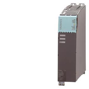
Дизайн
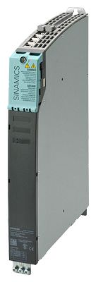
Double Motor Modules feature the following connections and interfaces as standard:
- 2 DC link connections via integrated DC link busbars
- 2 electronics power supply connections via integrated 24 V DC busbars
- 4 DRIVE‑CLiQ sockets
- 2 plug-in motor connections
(not included in scope of supply) - 2 safe standstill inputs (1 input per axis)
- 2 safe motor brake controls
- 2 temperature sensor inputs (KTY84-130 or PTC)
- 3 PE (protective earth) connections
The status of the Motor Modules is indicated via two multi-color LEDs.
On Double Motor Modules, the motor cable shield can be connected in the connector.
The signal cable shield can be connected to the Motor Module by means of a shield connection terminal, e.g. Weidmüller type KLBÜ 3‑8 SC.
The scope of supply of the Motor Modules includes:
- DRIVE‑CLiQ cable appropriate to the width of the Motor Module for connection to the adjacent Motor Module, length = width of Motor Module + 0.06 m (0.20 ft)
- 2 blanking plugs for sealing unused DRIVE-CLiQ sockets
- Jumper for connecting the 24 V DC busbar to the adjacent Motor Module
- Connectors X21 and X22
- Device fans for cooling power units on modules with internal and external air cooling supplied from the internal voltage levels
- 1 set of warning labels in 30 languages
Характеристика
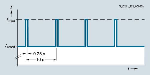
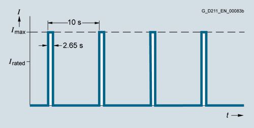
Overload capability
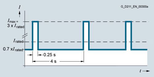
Peak current duty cycle with full load (300% overload)
Note:
Imax stands for 2 x Irated in the following overload characteristics.
Load cycle with previous load
Load cycle without previous load

S6 load cycle with previous load with a load cycle period of 600 s
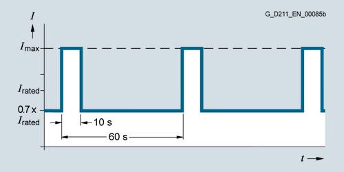
S6 load cycle with previous load with a load cycle period of 60 s
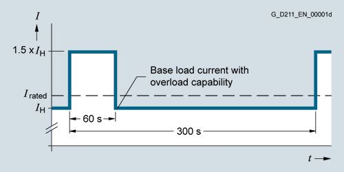
Load cycle with 60 s overload with a load cycle period of 300 s
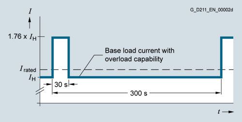
Load cycle with 30 s overload with a load cycle period of 300 s
Derating characteristics
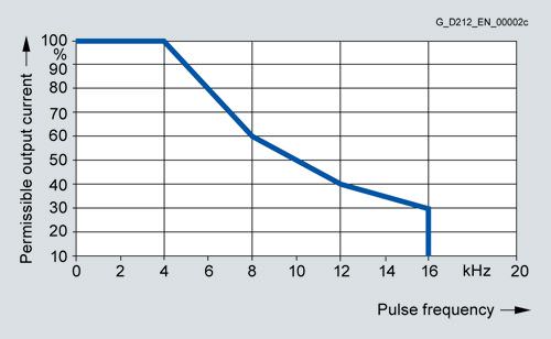
Output current dependent on pulse frequency
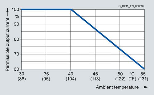
Output current dependent on ambient temperature
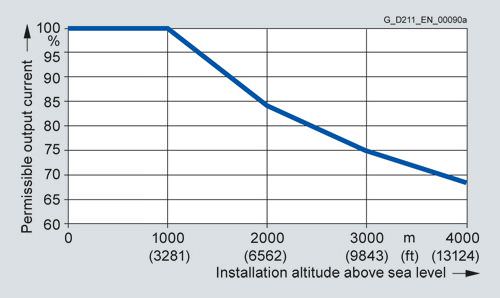
Output current dependent on installation altitude
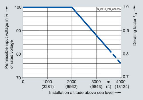
Voltage derating dependent on installation altitude
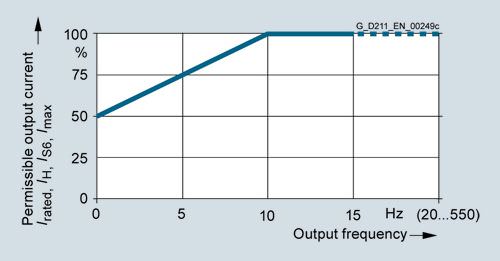
Current derating dependent on output frequency
Интеграция
The Double Motor Module communicates with the Control Unit via DRIVE‑CLiQ.
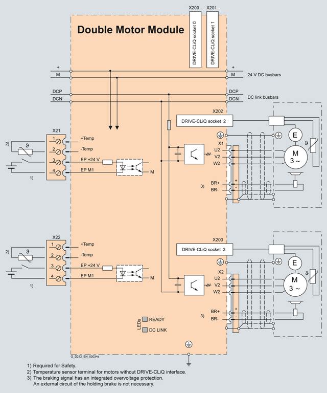
Connection example of Double Motor Modules in booksize format 2 × 3 A to 2 × 18 A
Технические данные
Double Motor Module in booksize format 6SL312... |
|
|---|---|
DC link voltage (up to 2000 m (6562 ft) above sea level) | 510 ... 720 V DC |
Output frequency |
|
| 0 ... 650 Hz 1) 2) |
| 0 ... 300 Hz 1) |
| 0 ... 600 Hz 1) 2) |
Electronics power supply | 24 V DC -15 %/+20 % |
Type of cooling | Internal air cooling, external air cooling, |
Permissible ambient and coolant temperature (air) during operation for line-side components, Line Modules and Motor Modules | 0 ... 40 °C (32 ... 104 °F) without derating, |
Installation altitude | Up to 1000 m (3281 ft) above sea level without derating, |
Declarations of conformity | CE (Low-Voltage and EMC Directives) |
Approvals, according to | cULus |
Safety Integrated | Safety Integrity Level 2 (SIL 2) acc. to IEC 61508, Performance Level d (PL d) acc. to ISO 13849‑1 and Control Category 3 acc. to ISO 13849‑1 or EN 954‑1 For further information, see section Safety Integrated.. |
1) Note the correlation between max. output frequency, pulse frequency and current derating.For more information, see section System description - Dimensioning.
2) The output frequency is currently limited to 550 Hz. The specified values apply to systems with license for high output frequency. For further information, refer to section Control Units and http://support.automation.siemens.com/WW/view/en/104020669
DC link voltage 510 ... 720 V DC | Double Motor Module in booksize format | ||||
|---|---|---|---|---|---|
Internal air cooling | 6SL3120-... | 2TE13-0AA4 | 2TE15-0AA4 | 2TE21-0AA4 | 2TE21-8AA3 |
External air cooling | 6SL3121-... | 2TE13-0AA4 | 2TE15-0AA4 | 2TE21-0AA4 | 2TE21-8AA3 |
Output current |
|
|
|
|
|
| A | 2 × 3 | 2 × 5 | 2 × 9 | 2 × 18 |
| A | 2 × 3.5 | 2 × 6 | 2 × 10 | 2 × 24 |
| A | 2 × 2.6 | 2 × 4.3 | 2 × 7.7 | 2 × 15.3 |
| A | 2 × 9 | 2 × 15 | 2 × 27 | 2 × 36 |
Type rating 1) |
|
|
|
|
|
| kW (HP) | kW (HP) | 2 × 1.6 (1.5) | 2 × 2.7 (3) | 2 × 4.8 (5) |
| kW (HP) | kW (HP) | 2 × 1.4 (1) | 2 × 2.3 (2.5) | 2 × 4.1 (5) |
DC link current Id2) | A | 7.2 | 12 | 22 | 43 |
Current carrying capacity |
|
|
|
|
|
| A | 100 | 100 | 100 | 100 |
| A | 20 | 20 | 20 | 20 |
DC link capacitance | μF | 110 | 220 | 220 | 705 |
Power requirement At 24 V DC, max. | A | 1.15 | 1.15 | 1.15 | 1 |
Internal/external air cooling |
|
|
|
|
|
|
|
|
|
|
|
| kW | 0.1 | 0.13 | 0.19 | 0.35 |
| kW | 0.05 | 0.08 | 0.15 | 0.28 |
| kW | 0.06/0.035 | 0.07/0.06 | 0.09/0.095 | 0.105/0.24 |
| m3/s (ft3/s) | 0.008 (0.3) | 0.008 (0.3) | 0.008 (0.3) | 0.008 (0.3) |
| dB | <60 | <60 | <60 | <60 |
Motor connection U2, V2, W2 |
| 2 x plug-in connectors (X1, X2) 5), | 2 x plug-in connectors (X1, X2) 5), | 2 x plug-in connectors (X1, X2) 5), | 2 x plug-in connectors (X1, X2) 5), |
Shield connection |
| Integrated in connector (X1, X2) | Integrated in connector (X1, X2) | Integrated in connector (X1, X2) | Integrated in connector (X1, X2) |
PE connection |
| M5 screw | M5 screw | M5 screw | M5 screw |
Motor brake connection |
| Integrated into the plug-in motor connector (X1, X2), 24 V DC, 2 A | Integrated into the plug-in motor connector (X1, X2), 24 V DC, 2 A | Integrated into the plug-in motor connector (X1, X2), 24 V DC, 2 A | Integrated into the plug-in motor connector (X1, X2), 24 V DC, 2 A |
Motor cable length, max. |
|
|
|
|
|
| m (ft) | 50 (164) | 50 (164) | 50 (164) | 70 (230) |
| m (ft) | 75 (246) | 75 (246) | 75 (246) | 100 (328) |
Degree of protection |
| IP20 | IP20 | IP20 | IP20 |
Dimensions |
|
|
|
|
|
| mm (in) | 50 (1.97) | 50 (1.97) | 50 (1.97) | 100 (3.94) |
| mm (in) | 380 (14.96) | 380 (14.96) | 380 (14.96) | 380 (14.96) |
|
|
|
|
|
|
| mm (in) | 270 (10.63) | 270 (10.63) | 270 (10.63) | 270 (10.63) |
| mm (in) | 226/66.5 (8.90/2.62) | 226/66.5 (8.90/2.62) | 226/66.5 (8.90/2.62) | 226/66.5 (8.90/2.62) |
Weight, approx. |
|
|
|
|
|
| kg (lb) | 5.3 (11.7) | 5.3 (11.7) | 5.3 (11.7) | 6.8 (15.0) |
| kg (lb) | 5.8 (12.8) | 5.8 (12.8) | 5.7 (12.6) | 8.6 (19.0) |
1) Rated power of a typical standard asynchronous (induction) motor at 600 V DC link voltage.
2) Rated DC link current for dimensioning an external DC connection.
For DC link current calculation for dimensioning the Line Module, see chapter System description – Dimensioning.
3) If, due to a number of Line Modules and Motor Modules being mounted side-by-side, the current carrying capacity exceeds 20 A, an additional 24 V DC connection using a 24 V terminal adapter is required (max. cross-section 6 mm2, max. fuse protection 20 A).
4) Power loss of Motor Module at rated power including losses of 24 V DC electronics power supply.
5) Connector not included in scope of supply, see Accessories.
6) At max. motor cable length 30 m (98.43 ft), pulse frequency 4 kHz and DC link voltage 540 ... 600 V.


 Ответ от производителя может занять до 5 дней и более.

