Single Motor Modules Siemens
Дизайн
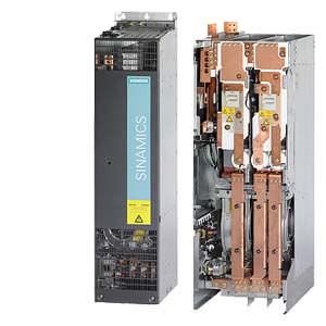
The Single Motor Modules in chassis format feature the following connections and interfaces as standard:
- 1 DC link connection (DCP, DCN) for connecting to the supply DC busbar
- 1 DC link connection (DCPA, DCNA) for connecting a Braking Module
- 1 electronic power supply connection
- 3 DRIVE‑CLiQ sockets
- 1 motor connection
- 1 safe standstill input (enable pulses)
- 1 temperature sensor input (KTY84-130, PT100 two-wire or PTC)
- 1 PE/protective conductor connection
The status of the Motor Modules is indicated via two multi-color LEDs.
The scope of supply of the Motor Modules includes:
- Frame sizes FX and GX:
- 0.60 m (1.97 ft) DRIVE-CLiQ cable for connection to the adjacent Motor Module
Характеристика
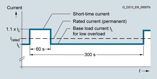
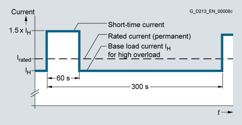
Overload capability
Load cycle data for Single Motor Modules in chassis format
The base-load current IL is based on a duty cycle of 110% for 60 s or 150% for 10 s with a duty cycle duration of 300 s.
Low overload
The base-load current IH is based on a duty cycle of 150% for 60 s or 160% for 10 s with a duty cycle duration of 300 s.
High overload
Derating factors
When the pulse frequency is increased, the derating factor of the output current must be taken into account.
This derating factor must be applied to the currents specified in the technical data.
Derating factor of the output current as a function of the pulse frequency for devices with a rated pulse frequency of 2 kHz
Single Motor Module in chassis format | Type rating | Output current | Derating factor |
|---|---|---|---|
Type |
| for a pulse frequency of 2 kHz | for a pulse frequency of 4 kHz |
6SL3320- ... | kW (HP) | A |
|
1TE32‑1AA3 | 110 (150) | 210 | 0.82 |
1TE32‑6AA3 | 132 (200) | 260 | 0.83 |
1TE33‑1AA3 | 160 (250) | 310 | 0.88 |
1TE33‑8AA3 | 200 (300) | 380 | 0.87 |
1TE33‑0AA3 | 250 (400) | 490 | 0.78 |
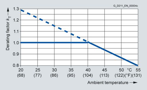
Current derating as a function of the ambient temperature
Note: A derating factor kT > 1.0 is applicable only in conjunction with "current derating as a function of installation altitude". The rated current data may not be exceeded. For further information see System description.
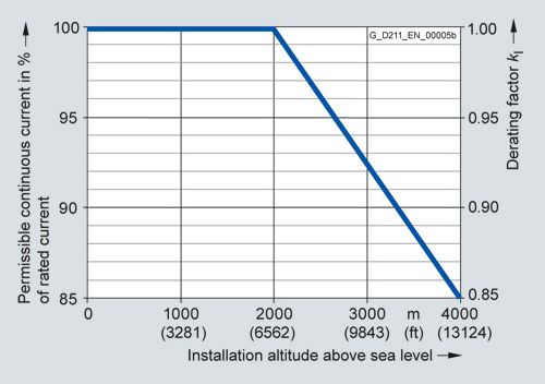
Current derating as a function of the installation altitude

Voltage derating as a function of installation altitude
Интеграция
The Single Motor Module receives its control information via DRIVE-CLiQ from:
- CU320-2 Control Unit
- SINUMERIK 840D sl with
- NCU 710.3 PN
- NCU 720.3 PN
- NCU 730.3 PN
- Numeric Control Extensions NX10.3/NX15.3
Технические данные
Product name | Single Motor Modules in chassis format |
|---|---|
6SL3320-... | |
DC link voltage Up to 2000 m (6562 ft) above sea level | 510 ... 720 V DC (line supply voltage 380 ... 480 V 3 AC) |
Output frequency | 0 … 300 Hz 1) |
Electronic power supply | 24 V DC -15 %/+20 % |
Cooling method | Internal air cooling, |
Permissible ambient or coolant temperature (air) In operation for line-side components, Line Modules and Motor Modules | 0 … 40 °C (32 … 104 °F) without derating, |
Installation altitude | Up to 2000 m (6562 ft) above sea level without derating, |
Declarations of conformity | CE (Low Voltage and EMC Directives) |
Approvals, according to 510 ... 720 V DC Motor Modules only | cULus |
Safety Integrated | Safety Integrity Level 2 (SIL 2) according to IEC 61508, |
1) Note correlation between max. output frequency, pulse frequency and current derating (250 µs current controller cycle; 4 kHz pulse frequency, see characteristics for derating).
DC link voltage 510 … 720 V DC | Single Motor Module in chassis format | |||||
|---|---|---|---|---|---|---|
| 6SL3320-... | 1TE32‑1AA3 | 1TE32‑6AA3 | 1TE33‑1AA3 | 1TE33‑8AA3 | 1TE35‑0AA3 |
Output current |
|
|
|
|
|
|
| A | 210 | 260 | 310 | 380 | 490 |
| A | 205 | 250 | 302 | 370 | 477 |
| A | 178 | 233 | 277 | 340 | 438 |
| A | 230 | 285 | 340 | 430 | 540 |
| A | 307 | 375 | 453 | 555 | 715 |
Type rating 1) |
|
|
|
|
|
|
| kW (HP) | 110 (150) | 132 (200) | 160 (250) | 200 (300) | 250 (400) |
| kW (HP) | 90 (125) | 110 (150) | 132 (200) | 160 (250) | 200 (350) |
Rated pulse frequency | kHz | 2 | 2 | 2 | 2 | 2 |
Rated DC link current Id2) When supplied via |
|
|
|
|
|
|
| A | 227 | 281 | 335 | 411 | 530 |
DC link capacitance | μF | 4200 | 5200 | 6300 | 7800 | 9600 |
Current requirement |
|
|
|
|
|
|
| A | 0.9 | 0.9 | 1.2 | 1.2 | 1.2 |
| A | 0.63/0.95 | 1.13/1.7 | 1.8/2.7 | 1.8/2.7 | 1.8/2.7 |
Power loss, max. | kW | 1.94 | 2.6 | 3.1 | 3.8 | 4.5 |
Cooling air requirement | m3/s (ft3/s) | 0.17 (6.0) | 0.23 (8.1) | 0.36 (12.7) | 0.36 (12.7) | 0.36 (12.7) |
Sound pressure level LpA (1 m) | dB | < 67 | < 69 | < 69 | < 69 | < 69 |
DC link connection DCP, DCN |
| Flat connector for M10 screw | Flat connector for M10 screw | Flat connector for M10 screw | Flat connector for M10 screw | Flat connector for M10 screw |
| mm2 | 2 × 185 | 2 × 185 | 2 × 185 | 2 × 185 | 2 × 185 |
Motor connection U2, V2, W2 |
| Flat connector for M10 screw | Flat connector for M10 screw | Flat connector for M10 screw | Flat connector for M10 screw | Flat connector for M10 screw |
| mm2 | 2 × 185 | 2 × 185 | 2 × 185 | 2 × 185 | 2 × 185 |
PE connection |
| M10 screw | M10 screw | M10 screw | M10 screw | M10 screw |
| mm2 | 2 × 185 | 2 × 185 | 2 × 185 | 2 × 185 | 2 × 185 |
Motor brake connection |
| – | – | – | – | – |
Motor cable length, max. Without external options |
|
|
|
|
| |
| m (ft) | 300 (984) | 300 (984) | 300 (984) | 300 (984) | 300 (984) |
| m (ft) | 450 (1476) | 450 (1476) | 450 (1476) | 450 (1476) | 450 (1476) |
Degree of protection |
| IP20 | IP20 | IP20 | IP20 | IP20 |
Dimensions |
|
|
|
|
|
|
| mm (in) | 326 (12.83) | 326 (12.83) | 326 (12.83) | 326 (12.83) | 326 (12.83) |
| mm (in) | 1400 (55.12) | 1400 (55.12) | 1533 (60.35) | 1533 (60.35) | 1533 (60.35) |
| mm (in) | 356 (14.02) | 356 (14.02) | 545 (21.46) | 545 (21.46) | 545 (21.46) |
Frame size |
| FX | FX | GX | GX | GX |
Weight, approx. | kg (lb) | 88 (194) | 88 (194) | 152 (335) | 152 (335) | 152 (335) |
1) Rated power of a typical standard asynchronous (induction) motor at 600 V DC link voltage.
2) Rated DC link current for dimensioning an external DC connection.


 Ответ от производителя может занять до 5 дней и более.

