Power Modules Siemens
Дизайн
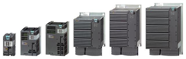
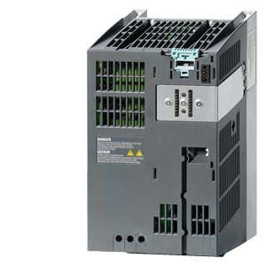
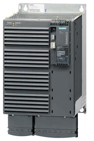
PM340 Power Modules in blocksize format, frame sizes FSA to FSF
The PM340 Power Modules in blocksize format feature the following connections and interfaces as standard:
- Line connection
- DCP/R1 and DCN DC link terminals
- PM-IF interface for connection of the PM340 Power Module and CU310-2 Control Unit or CUA31 Control Unit Adapter. The PM340 Power Module also supplies power to the CU310-2 Control Unit or CUA31 Control Unit Adapter by means of an integrated power pack
• Terminals DCP/R1 and R2 for connection of an external braking resistor
• Motor connection made with screw-type terminals or screw studs
• Control circuit for the Safe Brake Relay for controlling a holding brake
• 2 PE/protective conductor connections
Power Modules without integrated line filter can be connected to grounded star (TN, TT) and non-grounded symmetrical IT systems. Power Modules with integrated line filter are suitable only for connection to TN systems with grounded star points.
The integrated Braking Module (Braking Chopper) is rated such that it can connect the external braking resistor continuously. The temperature of the external braking resistor must be monitored to provide protection against thermal overloading.
Характеристика
Overload capability
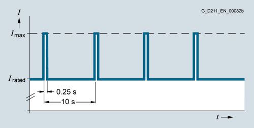
Load cycle with previous load
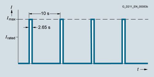
Load cycle without previous load

S6 load cycle with previous load with a load cycle period of 600 s
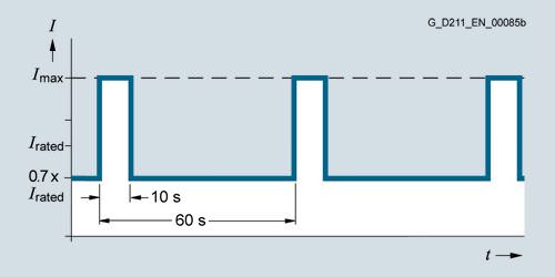
S6 load cycle with previous load with a load cycle period of 60 s
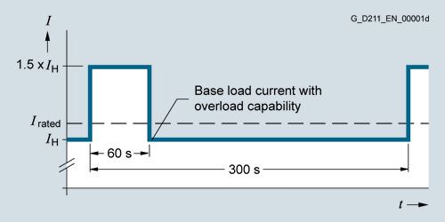
Load cycle with 60 s overload with a load cycle period of 300 s
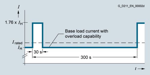
Load cycle with 30 s overload with a load cycle period of 300 s
Derating characteristics
- Frame sizes FSA to FSE

Output current as a function of pulse frequency
- Frame size FSF

Output current as a function of pulse frequency
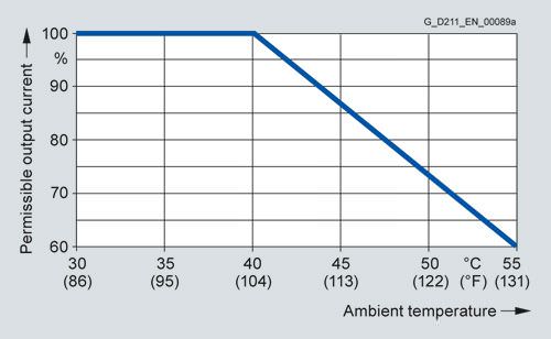
Output current as a function of ambient temperature
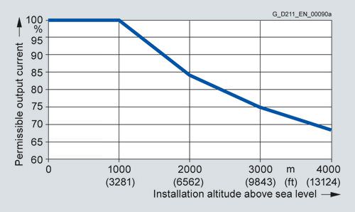
Output current as a function of installation altitude
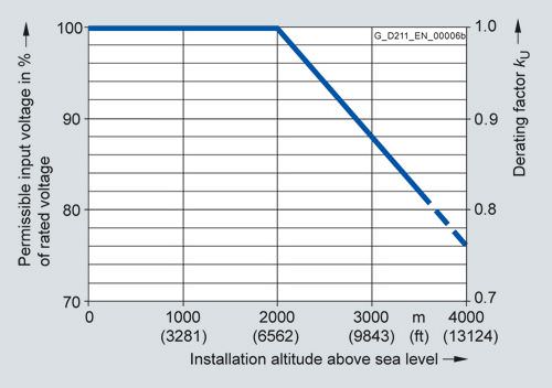
Voltage derating as a function of installation altitude
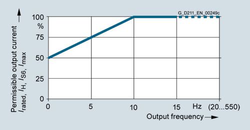
Output current as a function of output frequency
Интеграция
The PM340 Power Modules in blocksize format communicate with the CU310-2 Control Unit or the CUA31 Control Unit Adapter via the PM-IF interface.

PM340 Power Module in blocksize format with CU310-2 PN Control Unit
PM340 Power Module in blocksize format with CUA31 Control Unit Adapter
Many system components for PM340 Power Modules are designed as base components, i.e. the component is mounted on the baseplate and the PM340 Power Module in front of them in a space-saving construction. Up to two base components can be mounted in front of one another.
FSA | FSB | FSC | FSD | FSE | FSF | |
|---|---|---|---|---|---|---|
Line filter | ✓ | – | – | – | – | – |
Line reactor | ✓ | ✓ | ✓ | ✓ | ✓ | O |
Braking resistor | ✓ | ✓ | O | O | O | O |
✓ = Suitable as base-type
O = Not suitable as base-type
– = Not available (use Power Modules with integrated line filter)
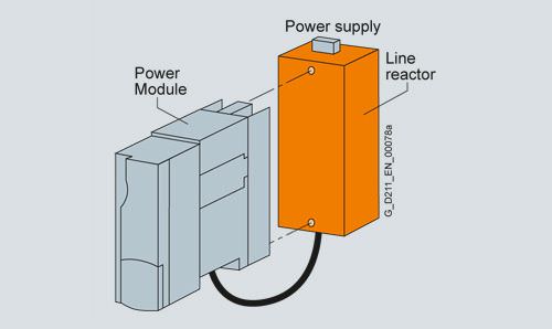
Basic layout of a PM340 Power Module with line reactor as base component
The line-side reactors are equipped with terminals and the reactors at the Power Module end with a pre-assembled cable. When installed, the mains terminals are at the top on frame sizes FSA to FSC, and at the bottom on frame sizes FSD and FSE.

Power Module PM340 frame size FSA with line reactor and line filter
If a line filter is installed in addition to the line reactor on frame size FSA, the components must be arranged as shown in the figure above. In this case, the line connection is below.
Power Modules of frame size FSB and higher are available with integrated line filters, alleviating the need for an external line filter.
For configurations involving more than two base-type system components, individual components must be mounted to the side of the Power Module. In this instance, the line reactor must be installed behind the Power Module and the braking resistor to the side.
Технические данные
Product name | Power Modules in blocksize format |
6SL3210-... | |
Line supply voltage Up to 2000 m (6562 ft) above sea level | 200 V ... 240 V 1 AC ±10 % 380 ... 480 V 3 AC ±10 % |
Line frequency | 47 … 63 Hz |
Line power factor With rated power |
|
| > 0.96 |
|
|
| 0.45 … 0.7 |
| 0.65 … 0.95 |
Overvoltage category In accordance with EN 60664-1 | Class III |
Precharging frequency Of the DC link, max. | 1× every 30 s |
DC link voltage, approx. | 1.35 × line voltage |
Output frequency | 0 … 650 Hz 1) |
Electronic power supply | 24 V DC -15 %/+20 % |
Radio interference suppression |
|
| No radio interference suppression |
| Category C2 according to EN 61800‑3 |
Cooling method | Increased air cooling by means of built-in fan |
Permissible ambient or coolant temperature (air) In operation for line-side components, Power Modules | 0 … 40 °C (32 … 104 °F) without derating, |
Installation altitude | Up to 1000 m (3281 ft) above sea level without derating, |
Declarations of conformity | CE (Low Voltage and EMC Directives) |
Approvals, according to | cULus |
Safety Integrated | Safety Integrity Level 2 (SIL 2) according to IEC 61508, |
1) Note the correlation between max. output frequency, pulse frequency and current derating.
Line supply voltage 200 … 240 V 1 AC | PM340 Power Module in blocksize format | |||
|---|---|---|---|---|
| 6SL3210-... | 1SB11‑0... | 1SB12‑3... | 1SB14‑0... |
Output current |
|
|
|
|
| A | 0.9 | 2.3 | 3.9 |
| A | 0.8 | 2.0 | 3.4 |
| A | 1.4 | 3.3 | 5.5 |
| A | 2.0 | 4.6 | 7.8 |
Type rating 1) Based on Irated | kW (HP) | 0.12 (0.2) | 0.37 (0.5) | 0.75 (0.75) |
Rated pulse frequency | kHz | 4 | 4 | 4 |
Power loss | kW | 0.06 | 0.075 | 0.11 |
Cooling air requirement | m3/s (ft3/s) | 0.005 (0.2) | 0.005 (0.2) | 0.005 (0.2) |
Sound pressure level LpA (1 m) | dB | < 45 | < 45 | < 45 |
24 V DC power supply For Control Unit | A | 1.0 | 1.0 | 1.0 |
Rated input current 2) With/without line reactor | A | 1.4/2.2 | 4/6 | 6.5/10 |
Resistance value External braking resistor | Ω | ≥ 180 | ≥ 180 | ≥ 180 |
Cable length To braking resistor, max. | m (ft) | 15 (49) | 15 (49) | 15 (49) |
Line connection L, N |
| Screw-type terminals | Screw-type terminals | Screw-type terminals |
| mm2 | 1.0 … 2.5 | 1.0 … 2.5 | 1.0 … 2.5 |
Motor connection U2, V2, W2 |
| Screw-type terminals | Screw-type terminals | Screw-type terminals |
| mm2 | 1.0 … 2.5 | 1.0 … 2.5 | 1.0 … 2.5 |
DC link connection, DCP/R1, DCN, R2 |
| Screw-type terminals | Screw-type terminals | Screw-type terminals |
| mm2 | 1.0 … 2.5 | 1.0 … 2.5 | 1.0 … 2.5 |
PE connection |
| M4 screw | M4 screw | M4 screw |
Motor cable length 3), max. Without external options |
|
|
|
|
| m (ft) | 50 (164) | 50 (164) | 50 (164) |
| m (ft) | 75 (246) | 75 (246) | 75 (246) |
Degree of protection |
| IP20 | IP20 | IP20 |
Dimensions |
|
|
|
|
| mm (in) | 73 (2.87) | 73 (2.87) | 73 (2.87) |
| mm (in) | 173 (6.81) | 173 (6.81) | 173 (6.81) |
|
|
|
|
|
| mm (in) | 145 (5.71) | 145 (5.71) | 145 (5.71) |
| mm (in) | 234.6 (9.24) | 234.6 (9.24) | 234.6 (9.24) |
| mm (in) | 175.3 (6.90) | 175.3 (6.90) | 175.3 (6.90) |
Frame size |
| FSA | FSA | FSA |
Weight, approx. | kg (lb) | 1.2 (2.65) | 1.3 (3) | 1.3 (3) |
1) Nominal HP based on asynchronous motors and 460 V AC. For specific sizing select drive based on motor nameplate current and overload.
2) The input current depends on the motor load and line impedance. The input currents apply for rated power loading (based on Irated) for a line impedance corresponding to uk = 1 %.
3) Max. motor cable length 15 m (49 ft) (shielded) for PM340 Power Modules with integrated line filter to maintain the limit values of EN 61800-3 Category C2.
Line supply voltage 380 … 480 V 3 AC | PM340 Power Module in blocksize format | |||||
|---|---|---|---|---|---|---|
| 6SL3210-... | 1SE11‑3UA0 | 1SE11‑7UA0 | 1SE12‑2UA0 | 1SE13‑1UA0 | 1SE14‑1UA0 |
Output current |
|
|
|
|
|
|
| A | 1.3 | 1.7 | 2.2 | 3.1 | 4.1 |
| A | 1.1 | 1.5 | 1.9 | 2.7 | 3.6 |
| A | 1.3 | 2.0 | 2.5 | 3.5 | 4.5 |
| A | 2.6 | 3.4 | 4.4 | 6.2 | 8.2 |
Type rating 1) |
|
|
|
|
|
|
| kW (HP) | 0.37 (0.5) | 0.55 (0.75) | 0.75 (1) | 1.1 (1.5) | 1.5 (2) |
| kW (HP) | 0.37 (0.5) | 0.55 (0.5) | 0.75 (0.75) | 1.1 (1) | 1.5 (2) |
Rated pulse frequency | kHz | 4 | 4 | 4 | 4 | 4 |
Power loss | kW | 0.10 | 0.10 | 0.10 | 0.11 | 0.11 |
Cooling air requirement | m3/s (ft3/s) | 0.005 (0.2) | 0.005 (0.2) | 0.005 (0.2) | 0.005 (0.2) | 0.005 (0.2) |
Sound pressure level LpA (1 m) | dB | < 45 | < 45 | < 45 | < 45 | < 45 |
24 V DC power supply For Control Unit | A | 1.0 | 1.0 | 1.0 | 1.0 | 1.0 |
Rated input current 2) With/without line reactor | A | 1.3/1.7 | 1.7/2.2 | 2.2/2.6 | 3.1/3.9 | 4.1/4.8 |
Resistance value External braking resistor | Ω | ≥ 390 | ≥ 390 | ≥ 390 | ≥ 390 | ≥ 390 |
Cable length To braking resistor, max. | m (ft) | 15 (49) | 15 (49) | 15 (49) | 15 (49) | 15 (49) |
Line connection U1/L1, V1/L2, W1/L3 |
| Screw-type terminals | Screw-type terminals | Screw-type terminals | Screw-type terminals | Screw-type terminals |
| mm2 | 1.0 … 2.5 | 1.0 … 2.5 | 1.0 … 2.5 | 1.0 … 2.5 | 1.0 … 2.5 |
Motor connection U2, V2, W2 |
| Screw-type terminals | Screw-type terminals | Screw-type terminals | Screw-type terminals | Screw-type terminals |
| mm2 | 1.0 … 2.5 | 1.0 … 2.5 | 1.0 … 2.5 | 1.0 … 2.5 | 1.0 … 2.5 |
DC link connection, DCP/R1, DCN, R2 |
| Screw-type terminals | Screw-type terminals | Screw-type terminals | Screw-type terminals | Screw-type terminals |
| mm2 | 1.0 … 2.5 | 1.0 … 2.5 | 1.0 … 2.5 | 1.0 … 2.5 | 1.0 … 2.5 |
PE connection |
| M4 screw | M4 screw | M4 screw | M4 screw | M4 screw |
Motor cable length 3), max. |
|
|
|
|
|
|
| m (ft) | 50 (164) | 50 (164) | 50 (164) | 50 (164) | 50 (164) |
| m (ft) | 75 (246) | 75 (246) | 75 (246) | 75 (246) | 75 (246) |
Degree of protection |
| IP20 | IP20 | IP20 | IP20 | IP20 |
Dimensions |
|
|
|
|
|
|
| mm (in) | 73 (2.87) | 73 (2.87) | 73 (2.87) | 73 (2.87) | 73 (2.87) |
| mm (in) | 173 (6.81) | 173 (6.81) | 173 (6.81) | 173 (6.81) | 173 (6.81) |
|
|
|
|
|
|
|
| mm (in) | 145 (5.71) | 145 (5.71) | 145 (5.71) | 145 (5.71) | 145 (5.71) |
| mm (in) | 234.6 (9.24) | 234.6 (9.24) | 234.6 (9.24) | 234.6 (9.24) | 234.6 (9.24) |
| mm (in) | 175.3 (6.90) | 175.3 (6.90) | 175.3 (6.90) | 175.3 (6.90) | 175.3 (6.90) |
Frame size |
| FSA | FSA | FSA | FSA | FSA |
Weight, approx. | kg (lb) | 1.2 (3) | 1.2 (3) | 1.2 (3) | 1.2 (3) | 1.2 (3) |
1) Nominal HP based on asynchronous motors and 460 V AC. For specific sizing select drive based on motor nameplate current and overload.
2) The input current depends on the motor load and line impedance. The input currents apply for rated power loading (based on Irated) for a line impedance corresponding to uk = 1 %.
3) Max. motor cable length 15 m (49 ft) (shielded) for PM340 Power Modules with integrated line filter to maintain the limit values of EN 61800-3 Category C2.
Line supply voltage 380 … 480 V 3 AC | PM340 Power Module in blocksize format | ||||||
|---|---|---|---|---|---|---|---|
| 6SL3210-... | 1SE16‑0... | 1SE17‑7... | 1SE21‑0... | 1SE21‑8... | 1SE22‑5... | 1SE23‑2... |
Output current |
|
|
|
|
|
|
|
| A | 5.9 | 7.7 | 10.2 | 18 | 25 | 32 |
| A | 5.2 | 6.8 | 9.1 | 14 | 21 | 27 |
| A | 6.4 | 8.3 | 10.8 | 19.6 | 27.8 | 37.1 |
| A | 11.8 | 15.4 | 20.4 | 26.4 | 38 | 52 |
Type rating 1) |
|
|
|
|
|
|
|
| kW (HP) | 2.2 (3) | 3 (5) | 4 (5) | 7.5 (10) | 11 (15) | 15 (20) |
| kW (HP) | 2.2 (3) | 3 (4) | 4 (5) | 5.5 (10) | 7.5 (15) | 11 (20) |
Rated pulse frequency | kHz | 4 | 4 | 4 | 4 | 4 | 4 |
Power loss | kW | 0.14 | 0.16 | 0.18 | 0.24 | 0.30 | 0.40 |
Cooling air requirement | m3/s (ft3/s) | 0.009 (0.3) | 0.009 (0.3) | 0.009 (0.3) | 0.038 (1.3) | 0.038 (1.3) | 0.038 (1.3) |
Sound pressure level LpA (1 m) | dB | < 50 | < 50 | < 50 | < 60 | < 60 | < 60 |
24 V DC power supply For Control Unit | A | 1.0 | 1.0 | 1.0 | 1.0 | 1.0 | 1.0 |
Rated input current 2) With/without line reactor | A | 5.6/6.7 | 7.5/8.9 | 9.8/12.4 | 17.1/23.1 | 24.6/32.6 | 33/39 |
Resistance value External braking resistor | Ω | ≥ 160 | ≥ 160 | ≥ 160 | ≥ 56 | ≥ 56 | ≥ 56 |
Cable length To braking resistor, max. | m (ft) | 15 (49) | 15 (49) | 15 (49) | 15 (49) | 15 (49) | 15 (49) |
Line connection U1/L1, V1/L2, W1/L3 |
| Screw-type terminals | Screw-type terminals | Screw-type terminals | Screw-type terminals | Screw-type terminals | Screw-type terminals |
| mm2 | 1.0 … 6 | 1.0 … 6 | 1.0 … 6 | 2.5 … 10 | 2.5 … 10 | 2.5 … 10 |
Motor connection U2, V2, W2 |
| Screw-type terminals | Screw-type terminals | Screw-type terminals | Screw-type terminals | Screw-type terminals | Screw-type terminals |
| mm2 | 1.0 … 6 | 1.0 … 6 | 1.0 … 6 | 2.5 … 10 | 2.5 … 10 | 2.5 … 10 |
DC link connection, DCP/R1, DCN, R2 |
| Screw-type terminals | Screw-type terminals | Screw-type terminals | Screw-type terminals | Screw-type terminals | Screw-type terminals |
| mm2 | 1.0 … 6 | 1.0 … 6 | 1.0 … 6 | 2.5 … 10 10 | 2.5 … 10 10 | 2.5 … 10 10 |
PE connection |
| M5 screw | M5 screw | M5 screw | M5 screw | M5 screw | M5 screw |
Motor cable length 3), max. |
|
|
|
|
|
|
|
| m (ft) | 50 (164) | 50 (164) | 50 (164) | 50 (164) | 50 (164) | 50 (164) |
| m (ft) | 75 (246) | 75 (246) | 75 (246) | 75 (246) | 75 (246) | 75 (246) |
Degree of protection |
| IP20 | IP20 | IP20 | IP20 | IP20 | IP20 |
Dimensions |
|
|
|
|
|
|
|
| mm (in) <Запрос коммерческого предложения× Сообщение отправлено× В ближайшее время сообщение будет обработано. Письмо с номером обращения отправлено на Ваш почтовый ящик. Спасибо за то, что выбрали Первый ZIP! Что-то пошло не так...× К сожалению, наша система расценила Ваше сообщение как спам. Если это произошло по ошибке, пожалуйста, обратитесь к нам по электронной почте. Приносим извинения за возможные неудобства.  Вы отправляете нам запрос  Если у нас есть прайс-лист, мы отправляем Вам ответ в течение дня. А если у нас нет прайс-листа по запрошенным товарам?     Если у нас нет прайс-листа, мы отправляем запрос производителю.  Ответ от производителя может занять до 5 дней и более. Ответ от производителя может занять до 5 дней и более.  Запрос производителю мы отправляем только для конечных потребителей.  Торгующим организациям коммерческие предложения предоставляются только по прайсовым позициям: Siemens Beckhoff Pepperl+Fuchs Phoenix Contact PILZ Turck Leuze Electronic Endress+Hauser Murr Elektronik Schmersal | ||||||