TM31 Terminal Module Siemens
Обзор
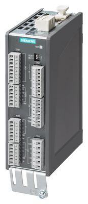
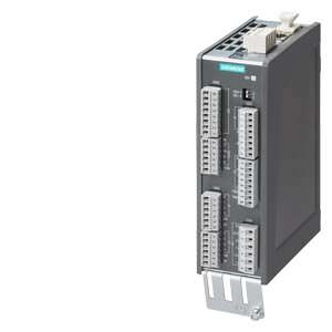
TM31 Terminal Module
With the TM31 Terminal Module, the number of available digital inputs and outputs and the number of analog input and outputs within a drive can be expanded.
The TM31 Terminal Module also features relay outputs with changeover contact and a temperature sensor input.
Дизайн
The following are located on the TM31 Terminal Module:
- 8 digital inputs
- 4 bidirectional digital inputs/outputs
- 2 relay outputs with changeover contact
- 2 analog inputs
- 2 analog outputs
- 1 temperature sensor input (KTY84‑130 or PTC)
- 2 DRIVE‑CLiQ sockets
- 1 connection for the electronics power supply via the 24 V DC supply connector
- 1 PE/protective conductor connection
The status of the TM31 Terminal Module is indicated via a multi-color LED.
The TM31 Terminal Module can be snapped onto a TH 35 top-hat rail to EN 60715 (IEC 60715).
The signal cable shield can be attached to the TM31 Terminal Module via a shield connection terminal, e.g. type SK8 supplied by Phoenix Contact or type KLBÜ CO 1 supplied by Weidmüller. The shield connection terminal must not be used as a strain relief mechanism.
Интеграция
The TM31 Terminal Module can communicate via DRIVE‑CLiQ with the following Control Units.
- CU310‑2 Control Unit
- CU320‑2 Control Unit
- SINUMERIK Control Unit
- SIMOTION D Control Unit
- SINAMICS DCM Advanced CUD
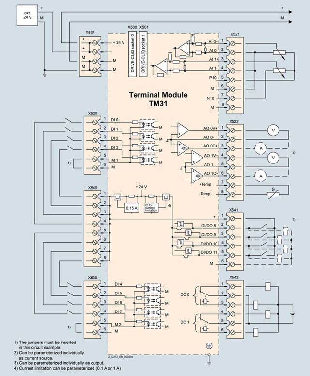
Connection example of TM31 Terminal Module
Технические данные
| TM31 Terminal Module 6SL3055-0AA00-3AA1 |
|---|---|
Power requirement, max. At 24 V DC without taking account of the digital outputs and DRIVE-CLiQ supply | 0.5 A |
| 2.5 mm2 |
| 20 A |
Digital inputs In accordance with IEC 61131‑2 Type 1 |
|
| -3 ... +30 V |
| -3 ... +5 V |
| 15 ... 30 V |
| 10 mA |
|
|
| 50 μs |
| 100 μs |
| 1.5 mm2 |
Digital outputs (continuously short-circuit proof) |
|
| 24 V DC |
| 100 mA |
| 400 mA |
|
|
| 150 μs with 0.5 A resistive load |
| 500 μs |
| 1.5 mm2 |
Analog inputs (a switch is used to toggle between voltage and current input) |
|
|
|
| -10 ... +10 V |
| 100 kΩ |
| 11 bits + sign |
|
|
| 4 ... 20 mA, -20 ... +20 mA, 0 ... 20 mA |
| 250 Ω |
| 10 bits + sign |
| 1.5 mm2 |
Analog outputs (continuously short-circuit proof) |
|
| -10 ... +10 V |
| -3 ... +3 mA |
| 4 ... 20 mA, -20 ... +20 mA, 0 ... 20 mA |
| 500 Ω for outputs in the range -20 ... +20 mA |
| 11 bit + sign |
| 1.5 mm2 |
Relay outputs (changeover contacts) |
|
| 8 A |
| 250 V AC, 30 V DC |
|
|
| 2000 VA (cos φ = 1) |
| 240 W (resistive load) |
| 100 mA |
| 2.5 mm2 |
Power loss, max. | 10 W |
PE connection | M4 screw |
Dimensions |
|
| 50 mm (1.97 in) |
| 150 mm (5.91 in) |
| 111 mm (4.37 in) |
Weight, approx. | 0.87 kg (2 lb) |
Approvals, according to | cULus |
1) The specified delay times refer to the hardware. The actual reaction time depends on the time slot in which the digital input/output is processed.
2) If the analog input is to be operated in the signal processing sense with continuously variable input voltage, the sampling frequency fa = 1/ttime slice must be at least twice the value of the highest signal frequency fmax.


 Ответ от производителя может занять до 5 дней и более.

