TM41 Terminal Module Siemens
Обзор
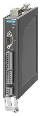
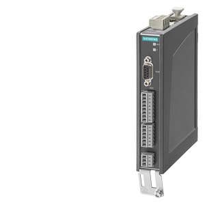
TM41 Terminal Module
The TM41 Terminal Module supplies TTL signals which emulate an incremental encoder, e.g. to a higher-level control. The encoder interface (incremental encoder emulation) can be linked to an encoder signal from the Control Unit, e.g. incremental encoder sin/cos, by parameter assignment.
The TM41 Terminal Module increases the number of digital inputs/outputs and analog inputs that are available in the drive system.
Дизайн
The following are located on the TM41 Terminal Module:
- 4 bidirectional digital inputs/outputs
- 4 digital inputs (with electrical isolation)
- 1 analog input
- 1 interface for emulation of TTL incremental encoder (RS422)
- 1 LED for signaling zero mark detection for encoder interface
- 2 DRIVE‑CLiQ sockets
- 1 connection for the 24 V DC supply of the digital outputs
- 1 connection for the electronics power supply via the 24 V DC supply connector
- 1 PE/protective conductor connection
The status of the TM41 Terminal Module is indicated via a multi-color LED.
An LED next to the interface for TTL pulse encoder emulation is illuminated as soon as a zero mark is detected.
The TM41 Terminal Module can be snapped onto a TH 35 standard mounting rail in accordance with EN 60715 (IEC 60715).
The signal cable shield can be connected to the TM41 Terminal Module via a shield connection terminal, e.g. type SK8 supplied by Phoenix Contact or type KLBÜ CO 1 supplied by Weidmüller. The shield connection terminal must not be used for strain relief.
Интеграция
The TM41 Terminal Module can communicate via DRIVE‑CLiQ with the following Control Units.
- CU310‑2 Control Unit
- CU320‑2 Control Unit
- SINUMERIK Control Unit
- SIMOTION D Control Unit
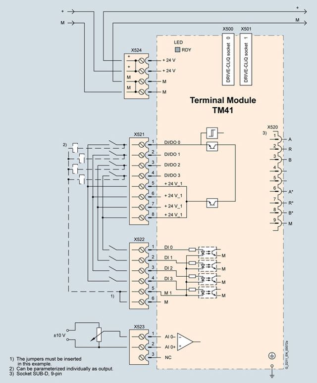
Connection example of TM41 Terminal Module
Технические данные
| TM41 Terminal Module 6SL3055-0AA00-3PA1 |
|---|---|
Current requirement (X524 at 24 V DC) without DRIVE-CLiQ supply or digital outputs (X514) | 0.5 A |
| 2.5 mm2 |
| 20 A |
I/O |
|
| Individually parameterizable as DI or DO |
| 4 |
| 4 |
| Plug-in screw-type terminals |
| 1.5 mm2 |
Digital inputs |
|
|
|
| -3 ... +30 V |
| -30 ... +30 V |
|
|
| -3 ... +5 V |
| -30 ... +5 V |
| 15 ... 30 V |
| <9 mA |
|
|
| 3 ms |
| 3 ms |
Digital outputs (sustained-short-circuit-proof) |
|
| 24 V DC |
| 0.5 A |
|
|
| 50 μs |
| 100 μs |
| 75 μs |
| 150 μs |
Analog input (difference) |
|
| -10 ... +10 V |
| ≥100 kΩ |
| 12 bits + sign |
Pulse encoder emulation |
|
| TTL (RS422), A+, A-, B+, B-, zero track N+, N- |
| 512 kHz |
| Any number of ratio/reduction ratio of pulses |
Power loss, max. | 10 W |
PE connection | M4 screw |
Dimensions |
|
| 30 mm (1.18 in) |
| 151 mm (5.94 in) |
| 110 mm (4.33 in) |
Weight, approx. | 0.32 kg (0.71 lb) |
Approvals, according to | cULus |
1) The specified delay times refer to the hardware. The actual reaction time depends on the time slot in which the digital input/output is processed.
2) If the analog input is to be operated in the signal processing sense with continuously variable input voltage, the sampling frequency fa = 1/ttime slot must be at least twice the value of the highest signal frequency fmax.


 Ответ от производителя может занять до 5 дней и более.

