Safe Brake Relay Siemens
Обзор
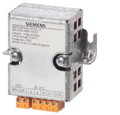
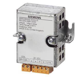
Safe Brake Relay
With the Safe Brake Relay, the brake is controlled in accordance with IEC 61508 SIL 2 and EN ISO 13849‑1 PL d and Category 3.
Дизайн
The Safe Brake Relay can be installed below the Power Module on the shield connection plate.
The Safe Brake Relay has the following connections and interfaces:
- 1 two-channel transistor output stage to control the motor brake solenoid
- 1 connection for the cable harness (CTRL) to the Power Module in blocksize format
- 1 connection for the 24‑V‑DC power supply
The connection between the 24 V DC supply and the Safe Brake Relay must be kept as short as possible.
The scope of supply of a Safe Brake Relay includes the following:
- 2 cable harnesses for connecting to the CTRL socket of the Power Module
- Length 0.32 m (1.05 ft) for frame sizes FSA to FSC
- Length 0.55 m (1.80 ft) for frame sizes FSD to FSF
Интеграция
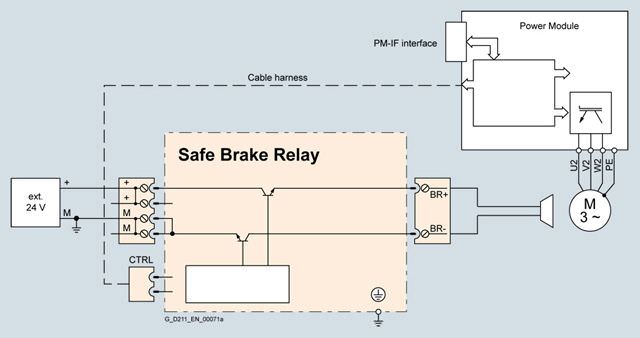
Connection example of a Safe Brake Relay
The 24 V DC solenoid of the motor brake is directly connected to the Safe Brake Relay. External overvoltage limiters are not required.
Технические данные
| Safe Brake Relay 6SL3252-0BB01-0AA0 |
|---|---|
Power supply | 20.4 ... 28.8 V DC Recommended rated supply voltage 26 V DC (to compensate for voltage drop in feeder cable to 24 V DC motor brake solenoid) |
Power requirement, max. |
|
| 2 A |
| 0.05 A + the current requirement of motor brake |
Conductor cross-section, max. | 2.5 mm2 |
Dimensions |
|
| 69 mm (2.72 in) |
| 63 mm (2.48 in) |
| 33 mm (1.30 in) |
Weight, approx. | 0.17 kg (0.37 lb) |


 Ответ от производителя может занять до 5 дней и более.

