SMC30 Sensor Module Cabinet-Mounted Siemens
Обзор
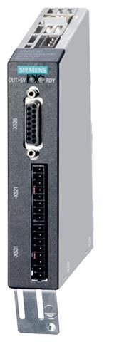
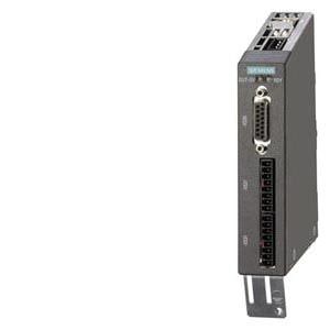
SMC30 Sensor Module Cabinet-Mounted
The SMC30 Sensor Module Cabinet-Mounted is required to evaluate the encoder signals of motors without a DRIVE‑CLiQ interface. External encoders can also be connected via the SMC30.
The following encoder signals can be evaluated:
- Incremental encoders TTL/HTL with/without open-circuit detection (open-circuit detection is only available with bipolar signals)
- SSI encoder with TTL/HTL incremental signals
- SSI encoder without incremental signals
The motor temperature can also be detected using KTY84‑130 or PTC thermistors.
Дизайн
The SMC30 Sensor Module Cabinet‑Mounted features the following connections and interfaces as standard:
- 1 encoder connection including motor temperature detection (KTY84‑130 or PTC) via SUB‑D connector or terminals
- 1 DRIVE-CLiQ interface
- 1 connection for the electronics power supply via the 24 V DC supply connector
- 1 PE (protective earth) connection
The status of the SMC30 Sensor Module Cabinet-Mounted is indicated via a multi-color LED.
The SMC30 Sensor Module Cabinet-Mounted can be snapped onto a TH 35 standard mounting rail in accordance with EN 60715 (IEC 60715).
The maximum encoder cable length between SMC30 modules and encoders is 100 m (328 ft). For HTL encoders, this length can be increased to 300 m (984 ft) if the A+/A- and B+/B- signals are evaluated and the power supply cable has a minimum cross section of 0.5 mm2.
The signal cable shield can be connected to the SMC30 Sensor Module Cabinet‑Mounted via a shield connection terminal, e.g., Phoenix Contact type SK8 or Weidmüller type KLBÜ CO 1. The shield connection terminal must not be used for strain relief.
Интеграция
SMC30 Sensor Modules Cabinet-Mounted communicate with a Control Unit via DRIVE‑CLiQ.
Технические данные
| SMC30 Sensor Module Cabinet-Mounted 6SL3055-0AA00-5CA2 |
|---|---|
Power requirement, max. at 24 V DC, | 0.2 A |
| 2.5 mm2 |
| 20 A |
Power loss, max. | 10 W |
Encoders which can be evaluated |
|
|
|
| 570 Ω |
| 16 mA |
| 24 V DC/0.35 A or 5 V DC/0.35 A |
| 300 kHz |
| 100 ... 1000 kBaud |
| 300 kHz |
| 30 bit |
|
|
| 100 m (328 ft) (only bipolar signals permitted)1) |
| 100 m (328 ft) for unipolar signals |
| 100 m (328 ft) |
PE connection | M4 screw |
Dimensions |
|
| 30 mm (1.18 in) |
| 150 mm (5.91 in) |
| 111 mm (4.37 in) |
Weight, approx. | 0.45 kg (1 lb) |
Approvals, according to | cULus |
1) Signal cables twisted in pairs and shielded.


 Ответ от производителя может занять до 5 дней и более.

