SME20/SME25 Sensor Modules External Siemens
Обзор
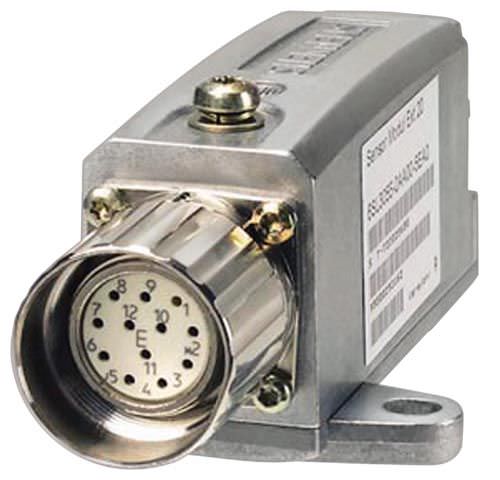
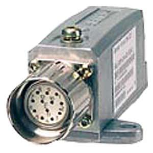
SME20/SME25 Sensor Module External
SME20/SME25 Sensor Modules External are encoder evaluation units for machine encoders (direct measuring systems).
The devices are designed with IP67 degree of protection. This means that the units can be installed outside the control cabinet near the machine encoder.
The following encoder signals can be evaluated:
- Incremental encoder sin/cos 1 Vpp without rotor position track (C and D tracks)
- Absolute encoder EnDat 2.1
- SSI absolute encoder 1) with incremental signals sin/cos 1 Vpp (firmware V2.4 and later)
Using adapter cable 6FX8002‑2CA88‑..., it is possible to connect a motor with a 17‑pole circular encoder connector to the 12-pole circular connector of the SME20.
- KTY/PTC temperature sensors can be used for motor temperature evaluation (only possible with SME20).
- The Sensor Module is only suitable for motors without absolute track signals (C and D tracks, e.g.:
- Synchronous motors with pole position identification (1FN, 1FW)
- Asynchronous motors (induction motors) (1PH)
SME20/SME25 Sensor Modules External evaluate the encoder signals and convert the information obtained to DRIVE-CLiQ. Neither motor nor encoder data are saved in the SME20/SME25.
1) For SME25, only encoders with 5 V supply voltage.
Дизайн
SME20/SME25 Sensor Modules External feature the following connenctions and interfaces as standard:
- 1 encoder connector via circular plug
- 1 DRIVE‑CLiQ interface with integrated 24 V DC electronics power supply from the Control Unit or Motor Module
- 1 PE (protective earth) connection
Интеграция
SME20/SME25 Sensor Modules External communicate with a Control Unit via DRIVE‑CLiQ.
Технические данные
| SME20 Sensor Module External 6SL3055-0AA00-5EA3 | SME25 Sensor Module External 6SL3055-0AA00-5HA3 | |
|---|---|---|---|
Encoders |
|
|
|
Signal subdivision (Interpolation) |
| ≤ 16384 times (14 bit) | ≤ 16384 times (14 bit) |
Max. encoder frequency that can be evaluated | kHz | ≤ 500 | ≤ 500 |
SSI/EnDat 2.1 baud rate | kHz | – | 100 |
Measuring system interface |
| 12-pin M23 circular connector | 17-pin M23 circular connector |
Outlet |
| IP67 DRIVE‑CLiQ connector | IP67 DRIVE‑CLiQ connector |
Power requirement, max. at 24 V DC, | A | 0.11 | 0.11 |
|
| Acc. to connector contacts | Acc. to connector contacts |
|
| Via DRIVE‑CLiQ power supply source | Via DRIVE‑CLiQ power supply source |
Power loss | W | < 4 | < 4 |
PE connection |
| M4 screw/1.8 Nm | M4 screw/1.8 Nm |
Cable length, max. |
|
|
|
| m (ft) | 3 (9.84) | 3 (9.84) |
| m (ft) | 100 (328) | 100 (328) |
Degree of protection |
| IP67 | IP67 |
Dimensions |
|
|
|
| mm (in) | 58 (2.28) | 58 (2.28) |
| mm (in) | 44 (1.73) | 44 (1.73) |
| mm (in) | 112 (4.41) | 112 (4.41) |
Weight, approx. | kg (lb) | 0.31 (0.7) | 0.31 (0.7) |
Approvals, according to |
| cULus | cULus |
1) The maximum cable length for the encoder system interface depends on the current consumption of the encoder system and the cross-section of the wires in the cable. However, the maximum length is 10 m (32.8 ft) (for further details, see the Equipment Manual SINAMICS S120 Control Units and supplementary system components).


 Ответ от производителя может занять до 5 дней и более.

