SME120/SME125 Sensor Modules External Siemens
Обзор
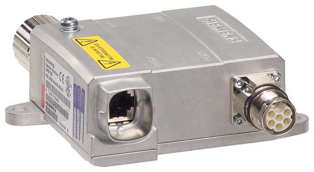
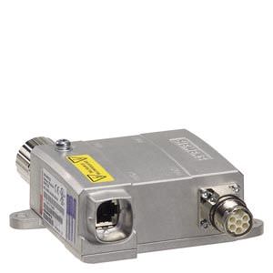
SME120/SME125 Sensor Module External
The SME120/SME125 Sensor Modules External are encoder evaluation units with degree of protection IP67, especially suitable for use in linear and torque motor applications. They can be installed close to the motor systems and encoders in the machine.
Sensor Modules External evaluate the encoder signals and motor temperature sensors specifically and convert the information obtained for DRIVE‑CLiQ. The motor temperature signals are safely electrically separated.
A Hall-effect sensor box can be connected for the SME120 to determine the commutation position of a linear motor.
Neither motor nor encoder data are saved in the SME120/SME125.
The SME120 and SME125 can be operated on Control Units with firmware release V2.4 and later.
The following encoder signals can be evaluated depending on the type of Sensor Module:
- Incremental encoder sin/cos 1 Vpp
- Absolute encoder EnDat 2.1
- SSI absolute encoder 1) with sin/cos 1 Vpp incremental signals, but without reference signal
The motor temperature can also be detected using KTY84‑130 or PTC thermistors.
1) For SME125, only SSI encoders with 5 V supply voltage.
Дизайн
SME120/SME125 Sensor Modules External feature the following connections and interfaces as standard:
- 1 encoder connection via circular connector
- 1 temperature sensor connection vai circular connector
- 1 Hall-effect sensor connection via circular connector (SME120 only)
- 1 DRIVE‑CLiQ interface with integrated 24 V DC electronics power supply from the Control Unit or Motor Module
- 1 PE (protective earth) connection
Технические данные
| SME120 Sensor Module External | SME125 Sensor Module External | |
|---|---|---|---|
| 6SL3055-0AA00-5JA3 | 6SL3055-0AA00-5KA3 | |
Encoders |
|
|
|
Signal subdivision (interpolation) |
| ≤ 16384 times (14 bit) | ≤ 16384 times (14 bit) |
Max. encoder frequency that can be evaluated | kHz | ≤ 500 | ≤ 500 |
SSI/EnDat 2.1 baud rate | kHz | – | 100 |
Measuring system interface |
| 12-pin M23 circular connector | 17-pin M23 circular connector |
Temperature sensor input |
| 6-pin M17 circular connector | 6-pin M17 circular connector |
Hall-effect sensor input |
| 9-pin M23 circular connector | – |
Output |
| IP67 DRIVE‑CLiQ connector | IP67 DRIVE‑CLiQ connector |
Power requirement, max. at 24 V DC, | A | 0.16 | 0.16 |
| A | 0.35 | 0.35 |
|
| Acc. to connector contacts | Acc. to connector contacts |
|
| Via DRIVE‑CLiQ power supply source | Via DRIVE‑CLiQ power supply source |
Power loss | W | ≤ 4.5 | ≤ 4.5 |
PE connection |
| M4 screw/1.8 Nm | M4 screw/1.8 Nm |
Cable length, max. |
|
|
|
| m (ft) | 3 (9.84) | 3 (9.84) |
| m (ft) | 100 (328) | 100 (328) |
Degree of protection |
| IP67 | IP67 |
Dimensions |
|
|
|
| mm (in) | 117.6 (4.63) | 117.6 (4.63) |
| mm (in) | 44 (1.73) | 44 (1.73) |
| mm (in) | 127 (5.00) | 127 (5.00) |
Weight, approx. | kg (lb) | 0.7 (1.5) | 0.7 (1.5) |
Approvals, according to |
| cULus | cULus |
1) The maximum cable length for the encoder system interface depends on the current consumption of the encoder system and the cross-section of the wires in the cable. However, the maximum length is 10 m (32.8 ft)(For further details, see the Equipment Manual SINAMICS S120 Control Units and supplementary system components).


 Ответ от производителя может занять до 5 дней и более.

