Measuring systems Siemens

Область применения
A distinction is made between incremental and absolute measuring procedures:
- In the case of incremental encoders, the machine must travel to a reference point after each power‑off state, as the position is not usually stored in the controller, and movements of the machine while the power is off are not recorded.
- Absolute encoders, on the other hand, also record these movements while the power is off and return the actual position with power On. Travel to a reference point is not necessary.
Обзор
Encoder type | Interface | Safety Integrated1) | Accuracy in angular seconds | Resolution | Degree of protection without/with |
|---|---|---|---|---|---|
Incremental encoders | |||||
 | sin/cos 1 Vpp | Yes | ± 18 mech. × 3600/ | 2500 S/R | IP67/IP64 |
RS422 (TTL) | 2) | ± 18 mech. × 3600/ | 5000 S/R | IP67/IP64 | |
HTL | 2) | ± 18 mech. × 3600/ | 2500 S/R | IP67/IP64 | |
RS422 (TTL) double track | 2) | Track 1: ± 63 | Track 1: 1024 S/R | IP67/IP64 | |
Absolute encoders | |||||
 | DRIVE‑CLiQ | 2) | ± 36 | Single‑turn Multi‑turn | IP67/IP64 |
 | SSI | 2) | ± 79 | Single‑turn Multi‑turn | IP67/IP64 |
EnDat | Yes | ± 60 | Single‑turn Multi‑turn | IP67/IP64 | |
 | PROFIBUS DP | 2) | ± 79 | Single-turn Multi-turn | IP67/IP64 |
 | PROFINET IO | 2) | ± 79 | Single-turn Multi-turn | IP67/IP64 |
S/R = signals/revolution
1) Built‑on rotary encoders can be used for Safety Integrated.
2) If you require information about the usability of built‑on rotary encoders for Safety Integrated, please contact your local Siemens office.
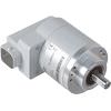
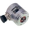
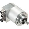
Absolute encoders, incremental encoders and mounting accessories
The built‑on optoelectronic rotary encoders sense distances, angles of rotation or speeds in machines. They can be used in conjunction with numerical control systems, programmable logic controllers, drives and position displays, e.g. for:
- SINUMERIK CNC controls
- SIMOTION Motion Control Systems
- SIMATIC programmable logic controllers
- SINAMICS drive systems
Дизайн
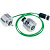
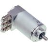
All encoders are available in Synchro flange and clamp flange versions. Encoders with a Synchro flange can be attached to the machine with 3 clamps or mounted with axial screws. The encoder is driven by means of a plug‑in coupling or a spring disk coupling. Alternatively, pulleys can also be used.
The encoder supply voltage is 5 V DC or alternatively 10 V to 30 V DC. The 10 V to 30 V DC version supports longer cable lengths. Most control systems apply the supply voltage directly on the measuring circuit connector. With SINAMICS, the power supply for the measuring systems is provided via the Sensor Modules.
For rotary encoders with cables, the cable length including the connector is 1 m (3.28 ft).
The following bending radii for the cables at the encoder must be observed:
- One‑time bending: ≥ 20 mm (0.79 in)
- Continuous bending: ≥ 75 mm (2.95 in)


 Ответ от производителя может занять до 5 дней и более.

