Incremental encoders Siemens
Функции
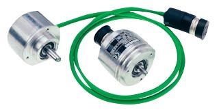
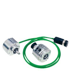
Incremental encoder (sin/cos 1 Vpp/RS422/HTL) with cable and connector, clamp flange or Synchro flange
Incremental encoders deliver a defined number of electrical pulses per revolution, which represent the measurement of the traveled distance or angle.
Incremental encoders operate on the principle of optoelectronic scanning of dividing discs with the transmitted light principle. The light source is a light emitting diode (LED). The light‑dark modulation generated as the encoder shaft rotates is picked up by photoelectronic elements. With an appropriate arrangement of the line pattern on the dividing disk connected to the shaft and the fixed aperture, the photoelectronic elements provide two trace signals A and B at 90° to one another, as well as a reference signal R. The encoder electronics amplify these signals and convert them into different output levels.
The following output levels are available:
- Analog signals sin/cos with 1 Vpp level
Better resolution can be achieved for encoders with sinusoidal signals by interpolating them in the higher‑level controller. - RS422 difference signals (TTL)
In the case of RS422 incremental encoders (TTL), the resolution can be improved by a factor of four by means of edge evaluation. - HTL (High Voltage Transistor Logic)
Encoders with HTL interfaces are designed for applications with digital inputs with 24 V levels.
Технические данные
Product name |
| Incremental encoder with sin/cos 1 Vpp | Incremental encoder with RS422 (TTL) | Incremental encoder with HTL | Double-track incremental encoder with RS422 (TTL) |
|---|---|---|---|---|---|
|
| 6FX2001‑3.... | 6FX2001‑2.... | 6FX2001‑4...0 | 6FX2001‑2UK00 |
Operating voltage DC | V | 5 | 5 | 10 ... 30 | 5 |
Limit frequency, typ. | kHz | ≥ 100 (-3 dB) | – | – | – |
Scanning frequency, max. | kHz | – | 300 | 300 | Track 1: 160 |
No‑load current consumption, max. | mA | 150 | 150 | 150 | Track 1: 150 |
Signal level | Sinusoidal 1 Vpp | RS422 (TTL) | VH ≥ 21 V | RS422 (TTL) | |
Outputs protected against short-circuit to 0 V | Yes | Yes | Yes | Yes | |
Switching time (10 ... 90%) | ns | – | ≤ 50 | ≤ 200 | ≤ 100 |
Phase angle, signal A to B | Degrees | 90 ± 10 | 90 | 90 | 90 |
| µs | – | – | – | Track 1: ≥ 0.8 |
| µs | – | ≥ 0.45 | ≥ 0.45 | – |
| µs | – | – | – | Track 2: ≥ 0.125 |
Cable length to downstream electronics, max.1) | M (ft) | 150 (492) | 100 (328) | 300 (984) | Up to 500 kHz: 100 (328) |
LED failure monitoring | – | High‑resistance driver | High‑resistance driver | – | |
Resolution, max. | S/R | 2500 | 5000 | 2500 | Track 1: 1024 |
Accuracy | arcsec | ± 18 mech. × 3600/PPR count z | ± 18 mech. × 3600/PPR count z | ± 18 mech. × 3600/PPR count z | Track 1: ± 63 |
Speed, max. | |||||
| rpm | (18 × 106 rpm)/PPR count | (18 × 106 rpm)/PPR count | (18 × 106 rpm)/PPR count | Track 1: 9000 |
| rpm | 12000 | 12000 | 12000 | 12000 |
Friction torque (at 20 °C) (68 °F) | Nm (lbf‑in) | ≤ 0.01 (0.09) | ≤ 0.01 (0.09) | ≤ 0.01 (0.09) | ≤ 0.01 (0.09) |
Starting torque (at 20 °C) (68 °F) | Nm (lbf‑in) | ≤ 0.01 (0.09) | ≤ 0.01 (0.09) | ≤ 0.01 (0.09) | ≤ 0.01 (0.09) |
Shaft loading capacity | |||||
| |||||
| N (lbf) | 40 (8.99) | 40 (8.99) | 40 (8.99) | 10 (2.25) |
| N (lbf) | 60 (13.5) | 60 (13.5) | 60 (13.5) | 20 (4.50) |
| |||||
| N (lbf) | 10 (2.25) | 10 (2.25) | 10 (2.25) | – |
| N (lbf) | 20 (4.50) | 20 (4.50) | 20 (4.50) | – |
Shaft diameter | |||||
| mm (in) | 6 (0.24) | 6 (0.24) | 6 (0.24) | 6 (0.24) |
| mm (in) | 10 (0.39) | 10 (0.39) | 10 (0.39) | – |
Shaft length | |||||
| mm (in) | 10 (0.39) | 10 (0.39) | 10 (0.39) | 15 (0.59) |
| mm (in) | 20 (0.79) | 20 (0.79) | 20 (0.79) | – |
Angular acceleration, max. | rad/s2 | 105 | 105 | 105 | 105 |
Moment of inertia of rotor | kgm2 (lbf‑in‑s2) | 1.45 × 10⁻⁶ (12.8 × 10⁻⁶) | 1.45 × 10⁻⁶ (12.8 × 10⁻⁶) | 1.45 × 10⁻⁶ (12.8 × 10⁻⁶) | 20 × 10-6 (177× 10-6) |
Vibration (55 ... 2000 Hz) acc. to EN 60068‑2‑6 | m/s2 (ft/s2) | ≤ 300 (984) | ≤ 300 (984) | ≤ 300 (984) | ≤ 100 (328) |
Shock acc. to EN 60068‑2‑27 | |||||
| m/s2 (ft/s2) | ≤ 2000 (6562) | ≤ 2000 (6562) | ≤ 2000 (6562) | – |
| m/s2 (ft/s2) | ≤ 1000 (3281) | ≤ 1000 (3281) | ≤ 1000 (3281) | ≤ 1000 (3281) |
Degree of protection acc. to EN 60529 (IEC 60529) | |||||
| IP67 | IP67 | IP67 | IP67 | |
| IP64 | IP64 | IP64 | IP64 | |
Ambient temperature | |||||
Operation | |||||
| |||||
| °C (°F) | ‑40 ... +100 (‑40 … +212) | ‑40 ... +100 (‑40 … +212) | ‑40 ... +100 (‑40 … +212) | ‑10 ... +70 (+14 … +158) |
| °C (°F) | – | ‑40 ... +70 (‑40 … +158) | – | – |
| |||||
| °C (°F) | ‑10 ... +100 (+14 … +212) | ‑10 ... +100 (+14 … +212) | ‑10 ... +100 (+14 … +212) | ‑10 ... +70 (+14 … +158) |
| °C (°F) | – | ‑10 ... +70 (+14 … +158) | – | – |
Weight, approx. | kg (lb) | 0.3 (0.66) | 0.3 (0.66) | 0.3 (0.66) | 0.7 (1.54) |
EMC | Tested in accordance with the guidelines for electromagnetic compatibility 89/336/EEC and the regulations of the EMC guidelines (generic standards) | ||||
Approvals, according to | CE, cULus | CE, cULus | CE, cULus | CE, cULus | |
S/R = signals/revolution
1) With recommended cable and input circuitry of the downstream electronics, observe max. permissible cable length of module to be evaluated.


 Ответ от производителя может занять до 5 дней и более.

