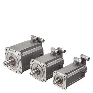
Built-in holding brakes for SIMOTICS S- 1FT7/1FK7 motors Siemens

Обзор
Built-in holding brakes for SIMOTICS S-1FT7/1FK7 motors
Many drives need a holding brake with an emergency stop function for safety reasons or to meet process requirements.
The permanent-magnet or spring-loaded, single-face brakes used for the 1FT7/1FK7 motors function according to the closed-circuit current principle. The magnetic field of the permanent-magnet exerts a tension on the brake anchor plate, i.e. in a condition of zero current, the brake is closed and the motor shaft thereby stopped. When the rated voltage of 24 V DC ± 10 % is applied to the brake, current flows through the coil and produces a counter-field that cancels the pull of the permanent-magnet, causing the brake to release.
The spring-loaded, single-face brake operates by the force of pressure exerted by the spring instead of a permanent-magnet. In the event of an emergency stop or power outage, approximately 2000 braking operations can be performed with the maximum switched energy without causing excessive wear on the holding brake (condition: maximum external moment of inertia = moment of inertia of motor and nmax type-specific).
The holding brake is not an operational brake.
In order to avoid switching overvoltages and any related effects on the plant environment, the brake cables must be connected externally with a varistor. The connection is made via the power connector or the terminal box.
When connected to the SINAMICS S120 drive system, this overvoltage protection is already included.
Технические данные
Motor | Built-in holding brake | ||||||
|---|---|---|---|---|---|---|---|
Shaft height | Type | Holding | Direct current | Opening time | Closing time | Moment | Maximum switched energy per brake operation from |
SH | J | ||||||
Nm (lbf-ft) | A | ms | ms | 10–4 kgm2 (10‑3 lbf-in-s2) | |||
1FT7 motors/with permanent-magnet brake, zero-backlash | |||||||
36 | 1FT703 | 3 (2.2) | 0.3 | 60 | 25 | 0.12 (0.11) | 30 |
48 | 1FT704 | 8 (5.9) | 0.6 | 90 | 30 | 0.87 (0.77) | 270 |
63 | 1FT706 | 18 (13.0) | 0.8 | 150 | 50 | 2.84 (2.51) | 880 |
80 | 1FT708 | 48 (35.4) | 1.0 | 220 | 65 | 15.4 (13.6) | 1900 |
100 | 1FT710 | 85 (62.7) | 1.6 | 250 | 70 | 27.6 (24.4) | 5300 |
1FK7 Compact/High Dynamic/High Inertia motors with permanent-magnet brake, zero-backlash | |||||||
10 | 1FK701 | 0.4 (0.3) | 0.3 | 30 | 20 | 0.019 (0.02) | 2 |
28 | 1FK7022 | 1.0 (0.74) | 0.3 | 30 | 20 | 0.07 (0.06) | 8 |
36 | 1FK703 | 1.9 (1.4) | 0.3 | 50 | 30 | 0.098 (0.087) | 40 |
48 | 1FK704 | 4.0 (2.95) | 0.5 | 70 | 30 | 0.32 (0.28) | 150 |
63 | 1FK706 | 13 (9.59) | 0.8 | 100 | 50 | 0.99 (0.88) | 380 |
80 | 1FK708 | 22 (16.2) | 0.9 | 200 | 60 | 3.28 (2.90) | 1400 |
100 | 1FK7100 | 23 (17.0) | 1.0 | 300 | 70 | 7.5 (6.64) | 3380 |
100 | 1FK7101 | 43 (31.7) | 1.0 | 300 | 70 | 7.5 (6.64) | 3380 |
1FK7-DYA geared servomotors and 1FK7 helical/bevel/parallel shaft/worm geared motors | |||||||
36 | 1FK7032 | 1.3 (0.96) | 0.4 | 50 | 30 | 0.08 (0.07) | 17 |
48 | 1FK704 | 3.2 (2.36) | 0.6 | 70 | 30 | 0.72 (0.64) | 74 |
63 | 1FK706 | 13 (9.59) | 0.8 | 100 | 50 | 2.25 (1.99) | 400 |
80 | 1FK7080 | 10 (7.38) | 0.7 | 100 | 50 | 3.1 (2.74) | 400 |
100 | 1FK7100 | 22 (16.2) | 0.9 | 200 | 60 | 8.6 (7.61) | 1400 |
100 | 1FK7101 | 41 (30.2) | 1.0 | 300 | 70 | 13.5 (11.95) | 3000 |
1) The holding torque is the highest permissible torque with which the closed brake can be loaded in steady-state operation without slip (holding function when motor is stationary).


 Ответ от производителя может занять до 5 дней и более.

