MOTION-CONNECT connection systems Siemens
- Length code
- Article number code power cables
- Article number code signal cables
- Accessories for power and signal cables
- Signal cables for SINAMICS
- Signal cables for SINUMERIK
- Power cables for SINAMICS S120
Область применения
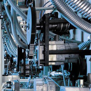
MOTION‑CONNECT cables are intended for use in machines. They are not suitable for building technology applications or outdoor installation.
MOTION‑CONNECT cables are tested in a cable carrier with horizontal travel distance and are also designed for cable carrier installation. They are not self-supporting.
The pre-assembled cables can be ordered in length units of 10 cm (3.94 in) and can be extended, if necessary.
When cable lengths (basic cables and extensions) are determined for the systems and applications described in this catalog, the technically permissible maximum cable lengths (e.g. 25 m (82 ft)) specified in the catalog must be observed. Malfunctions can occur if longer cables are used.
Siemens AG assumes no liability for correct transmission of signals or power in this case.
Compatibility between SPEED‑CONNECT and full-thread connectors:
Connector on motor with external thread | Connector with cap nut on cable | Compatibility |
|---|---|---|
SPEED‑CONNECT | SPEED‑CONNECT | ✓ |
SPEED‑CONNECT | Full-thread | ✓ |
Full-thread | Full-thread | ✓ |
Full-thread | SPEED‑CONNECT | – |
Обзор
MOTION‑CONNECT cables are suitable for use with many different types of machine tools and production machinery.
The following variants of MOTION‑CONNECT cable are available as fully-assembled power and signal cables or sold by the meter:
- MOTION‑CONNECT 500
- Cost-effective solution for predominantly fixed installation
- Suitable for low mechanical loading
- Tested for travel distances of up to 5 m (16.41 ft)
- Meets requirements for use in cable carriers
- Suitable for high mechanical loading
- Oil resistance
- Tested for travel distances of up to 50 m (164 ft)
Характеристика
Characteristic curves for MOTION‑CONNECT 800PLUS
The blue area beneath the characteristic curve represents the potential range of use for the cables. The characteristic curves represent the tested operating points.

Permissible acceleration for signal and power cables MOTION‑CONNECT 800PLUS up to 16 mm2
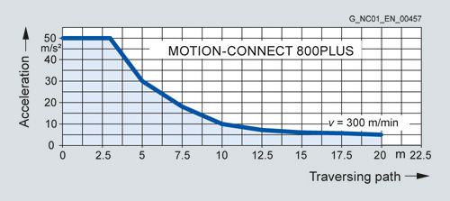
Permissible acceleration for power cables MOTION‑CONNECT 800PLUS with 25 mm2, 35 mm2 and 50 mm2
Функции
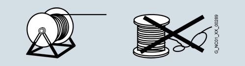
The cables must be removed from the drum without twisting, i.e. the cables must be unwound and must never be lifted over the drum flange in loops.
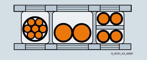
To maximize the service life of the cable carrier and cables, cables in the carrier made from different materials must be separated by spacers in the cable carrier. The spacers must be filled evenly to ensure that the position of the cables does not change during operation. The cables should be distributed as symmetrically as possible according to their weights and dimensions. Cables with very different outer diameters should also be separated by spacers.
When inserting pre-assembled cables into the cable carrier, do not pull at the connector, as this may damage the strain relief or cable clamping.
The cables must not be fixed in the cable carrier. They must be freely movable.
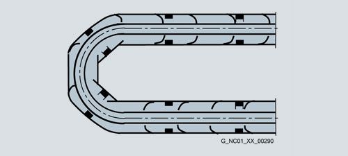
The cables must be able to be moved without applying force in particular in the bending radii of the carrier. The specified minimum bending radii must be adhered to.
The cable fixings must be attached at both ends at an appropriate distance away from the end points of the moving parts in a dead zone.

MOTION‑CONNECT cables are tested in a cable carrier. The cables are attached at one end by means of strain relief to the moving ends of the cable carrier. Strain relief is applied over a wide area of the cable jacket surface without crimping the cable.
Cables must be installed in accordance with the instructions supplied by the cable carrier manufacturer.
Notes:
If, for example, pre-assembled cables are installed in a cable carrier in such a way that the connector would inhibit assembly, pre-assembled cables without assembled connector can also be supplied (power and signal cables1)). In this case, the contacts of the cables are crimped and the connector enclosure is supplied separately. After installing the cables, the customer assembles the connector enclosure.
In case of vibration load and with horizontal or vertical cable entries, we recommend that the cable is additionally fixed if between the cable strain relief on the cable carrier and the terminal at the motor part of the cable is hanging loose or is not routed. To prevent machine vibrations being transmitted to the connectors, the cable should be fixed at the moving part where the motor is mounted.
Representation in connection overviews
Symbol | Explanation |
|---|---|
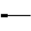 | Connector with pin contacts |
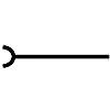 | Connector with socket contacts |
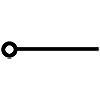 | Exposed core ends |
1) Not applicable to DRIVE‑CliQ signal cables.
Особенности
Pre-assembled MOTION‑CONNECT cables provide high quality and perfect, system-tested functionality.
SPEED‑CONNECT
Fast, stable and reliable connections can be made with the new, pre-assembled cables with SPEED‑CONNECT connectors. With a short rotation as far as the stop, the cap nut of the connector secures the connection.
The cables with SPEED‑CONNECT connectors supplement the established range of MOTION‑CONNECT cables with fully-threaded connectors.
Дальнейшая информация
Current carrying capacity for power and signal cables
The current carrying capacity of PVC/PUR-insulated copper cables is specified for installation types B1, B2, C and E under continuous operating conditions in the table with reference to an ambient air temperature of 40 °C (104 °F). For other ambient temperatures, the values must be corrected by the derating factors from the table.
Cross-section | Current carrying capacity rms AC 50/60 Hz or DC in amps for installation type | |||
|---|---|---|---|---|
B1 | B2 | C | E | |
mm2 | Single-core cables in protection tubes or installation ducts | Multi-core cables in protection tubes or installation ducts | Multi-core cables, vertically or horizontally on walls/open, without protection tubes and installation ducts/with contact | Multi-core cables, horizontally or vertically on perforated cable racks/open, without protection tubes and installation ducts/with contact |
Electronics1) | ||||
0.20 | – | 4.3 | 4.4 | 4.4 |
0.50 | – | 7.5 | 7.5 | 7.8 |
0.75 | – | 9 | 9.5 | 10 |
Power2) | ||||
0.75 | 8.6 | 8.5 | 9.8 | 10.4 |
1.00 | 10.3 | 10.1 | 11.7 | 12.4 |
1.50 | 13.5 | 13.1 | 15.2 | 16.1 |
2.50 | 18.3 | 17.4 | 21 | 22 |
4 | 24 | 23 | 28 | 30 |
6 | 31 | 30 | 36 | 37 |
10 | 44 | 40 | 50 | 52 |
16 | 59 | 54 | 66 | 70 |
25 | 77 | 70 | 84 | 88 |
35 | 96 | 86 | 104 | 110 |
50 | 117 | 103 | 125 | 133 |
70 | 149 | 130 | 160 | 171 |
95 | 180 | 165 | 194 | 207 |
120 | 208 | 179 | 225 | 240 |
1) One control circuit pair.
2) One symmetrically loaded three-phase AC cable.
Derating factors for power and signal cables
Ambient air temperature | Derating factor according to EN 60204-1, Table D.1 |
|---|---|
30 (86) | 1.15 |
35 (95) | 1.08 |
40 (104) | 1.00 |
45 (113) | 0.91 |
50 (122) | 0.82 |
55 (131) | 0.71 |
60 (140) | 0.58 |


 Ответ от производителя может занять до 5 дней и более.

