ARPEX ARP-6 series Siemens

Область применения
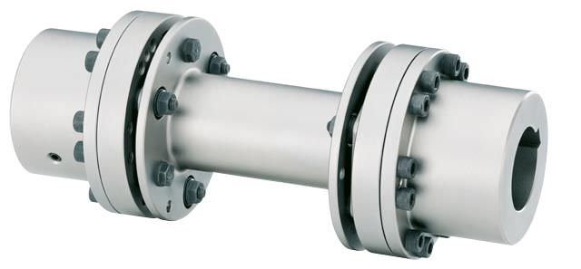
ARPEX series ARP-6 couplings have been specially developed for pump drives and specifically for centrifugal pump drives. Special care was taken to meet the requirements of API 610 and API 671 (API = American Petroleum Institute). Power is transmitted via close-fitting bolts and nuts from size 310-6 with conical screw connection and plate packs in hexagonal design. Torques of between 100 and 17000 Nm can be transmitted at a permitted angular misalignment of 0.7°. The closed flange shape and a compact construction permit high peripheral speeds and high speeds. The intermediate spacer can be fitted radially without moving the connected units.
Main areas of application for the ARP-6 series:
- Centrifugal pumps
- Boiler feed pumps
- Propeller pumps
- Wing pumps
- Pipeline pumps
- Turbo compressors
- Screw compressors
- Turbo blowers
- Axial, radial blowers
- Rotary-piston blowers
- Fans
Обзор

Coupling can be used for potentially explosive environments in accordance with 94/9/EC.
Дизайн
NAN: The design of an ARPEX NAN coupling of the ARP-6 series is shown in the following illustration. The plate packs are bolted alternately between the flanges of the coupling hubs and the intermediate spacer. Up to size 298-6 close-fitting bolts and from size 325-6 conical screw connections are used for fastening. The intermediate spacer is available from stock in various fixed lengths. Hubs are designed with threaded pull-off holes.
MCECM: The design of an ARPEX MCECM coupling of the ARP-6 series is shown in the following illustration. Bolted between two hubs is the CEC transmission unit, the preassembled plate packs of which are bolted alternately between flanges and intermediate spacer. Up to size 275-6 close-fitting bolts and from size 310-6 conical screw connections are used for fastening. The intermediate spacer is available from stock in various fixed lengths. Jumbo hubs for large bore diameters can be optionally used.
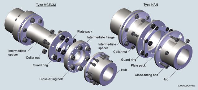
Design of the ARPEX coupling, ARP-6 series
Variants of the ARPEX coupling, ARP-6 series
Types | |
|---|---|
NAN | Variant with intermediate spacer, various fixed lengths available from stock |
MCECM | Variant with preassembled intermediate unit and spacer machined on all sides, various fixed lengths available from stock |
Further application-specific coupling types are available in selection module x.CAT at www.flender.com. Dimension sheets and further information are available on request.
Особенности
ARPEX couplings of the ARP-6 series are outstanding for their application-optimized construction. The two types NAN and MCECM have been specially designed for drives with uniform to medium loads and at the same time meet the requirements of API 610. The type MCECM with preassembled CEC intermediate unit can also be optionally designed to API 671. A special catcher device serves to secure the intermediate spacer in the event of plate breakage. Their use in potentially explosive environments in accordance with Directive 94/9/EC is possible.
Технические данные
Power ratings, type NAN
Size | Rated torque | Maximum torque | Overload torque | Fatique torque | Maximum speed | Maximum permitted shaft misalignment | Torsional stiffness | ||||||||||
|---|---|---|---|---|---|---|---|---|---|---|---|---|---|---|---|---|---|
TKN | TKmax | TKOL | TKW | nKmax | ±ΔKa | ±ΔKw | ±ΔKr | CT | |||||||||
S = 100 mm | S = 140 mm | S = 180 mm | S = 200 mm | S = 250 mm | S = 100 mm | S = 140 mm | S = 180 mm | S = 200 mm | S = 250 mm | ||||||||
Nm | Nm | Nm | Nm | rpm | mm | mm | mm | mm | mm | mm | MNm/rad | MNm/rad | MNm/rad | MNm/rad | MNm/rad | ||
88-6 | 190 | 270 | 450 | 70 | 21700 | 1.10 | 0.7° | 1.15 | 1.64 | – | – | – | 0.04 | 0.04 | – | – | – |
115-6 | 270 | 410 | 680 | 110 | 16600 | 1.81 | 1.15 | 1.64 | 2.13 | – | – | 0.09 | 0.09 | 0.08 | – | – | |
135-6 | 580 | 870 | 1450 | 230 | 12700 | 2.02 | 1.14 | 1.62 | 2.11 | – | – | 0.21 | 0.19 | 0.17 | – | – | |
150-6 | 660 | 100 | 1650 | 270 | 11400 | 2.41 | 1.14 | 1.62 | 2.11 | 2.36 | 2.97 | 0.27 | 0.25 | 0.24 | 0.23 | 0.21 | |
176-6 | 1220 | 1900 | 3100 | 490 | 9750 | 2.75 | 1.11 | 1.6 | 2.09 | 2.33 | 2.94 | 0.44 | 0.40 | 0.38 | 0.36 | 0.34 | |
185-6 | 1875 | 2900 | 4700 | 750 | 9300 | 2.85 | 1.09 | 1.58 | 2.06 | 2.31 | 2.92 | 0.56 | 0.52 | 0.49 | 0.47 | 0.44 | |
212-6 | 2850 | 4230 | 7200 | 1200 | 8100 | 3.06 | 1.10 | 1.59 | 2.08 | 2.32 | 2.93 | 0.81 | 0.75 | 0.70 | 0.67 | 0.62 | |
225-6 | 4200 | 6300 | 10500 | 1700 | 7650 | 3.14 | – | 1.59 | 2.08 | 2.32 | 2.93 | – | 0.85 | 0.81 | 0.79 | 0.74 | |
256-6 | 5750 | 8700 | 15000 | 2300 | 6700 | 3.69 | – | 1.56 | 2.05 | 2.3 | 2.91 | – | 1.37 | 1.31 | 1.29 | 1.22 | |
272-6 | 8050 | 12000 | 20000 | 3200 | 6300 | 3.85 | – | 1.51 | 2 | 2.25 | 2.86 | – | 1.44 | 1.39 | 1.36 | 1.3 | |
298-6 | 10000 | 15000 | 25000 | 4000 | 5150 | 4.19 | – | 1.47 | 1.95 | 2.2 | 2.81 | – | 1.47 | 1.43 | 1.41 | 1.37 | |
325-6 | 12000 | 18000 | 30000 | 4800 | 4700 | 4.45 | – | – | 1.93 | 2.17 | 2.79 | – | – | 2.48 | 2.44 | 2.34 | |
Power ratings, type MCECM
Size | Rated torque | Maximum torque | Overload torque | Fatique torque | Maximum speed | Maximum permitted shaft misalignment | Torsional stiffness | ||||||||||
|---|---|---|---|---|---|---|---|---|---|---|---|---|---|---|---|---|---|
TKN | TKmax | TKOL | TKW | nKmax | ±ΔKa | ±ΔKw | ±ΔKr | CT | |||||||||
S = 100 mm | S = 140 mm | S = 180 mm | S = 200 mm | S = 250 mm | S = 100 mm | S = 140 mm | S = 180 mm | S = 200 mm | S = 250 mm | ||||||||
Nm | Nm | Nm | Nm | rpm | mm | mm | mm | mm | mm | mm | MNm/rad | MNm/rad | MNm/rad | MNm/rad | MNm/rad | ||
64-4 | 100 | 150 | 250 | 40 | 22500 | 0.80 | 0.7° | 0.78 | 1.27 | – | – | – | 0.009 | 0.008 | – | – | – |
96-6 | 210 | 310 | 530 | 85 | 19900 | 1.15 | 0.78 | 1.27 | – | – | – | 0.06 | 0.05 | – | – | – | |
120-6 | 490 | 740 | 1250 | 200 | 15900 | 1.47 | 0.65 | 1.14 | 1.62 | – | – | 0.17 | 0.15 | 0.13 | – | – | |
142-6 | 925 | 1400 | 2300 | 370 | 13400 | 1.73 | – | 1.04 | 1.53 | – | – | – | 0.28 | 0.25 | – | – | |
162-6 | 1600 | 2400 | 4000 | 640 | 11800 | 2.07 | – | 0.92 | 1.40 | 1.65 | 2.26 | – | 0.43 | 0.39 | 0.38 | 0.34 | |
190-6 | 2500 | 3800 | 6300 | 1000 | 10000 | 2.36 | – | 0.93 | 1.42 | 1.66 | 2.27 | – | 0.71 | 0.65 | 0.63 | 0.57 | |
214-6 | 3900 | 5900 | 9800 | 1600 | 8900 | 2.67 | – | 0.78 | 1.27 | 1.51 | 2.13 | – | 1.01 | 0.94 | 0.92 | 0.85 | |
230-6 | 5200 | 7800 | 13000 | 2100 | 8300 | 2.88 | – | – | 1.25 | 1.49 | 2.10 | – | – | 1.36 | 1.32 | 1.22 | |
245-6 | 7000 | 10500 | 18000 | 2800 | 7800 | 2.99 | – | – | 1.00 | 1.25 | 1.86 | – | – | 1.49 | 1.45 | 1.37 | |
275-6 | 9800 | 15000 | 25000 | 4000 | 6250 | 3.38 | – | – | – | 1.22 | 1.83 | – | – | – | 1.65 | 1.58 | |
310-6 | 12900 | 20000 | 33000 | 5200 | 5550 | 3.85 | – | – | – | – | 1.64 | – | – | – | – | 2.96 | |
345-6 | 17000 | 26000 | 43000 | 6800 | 5000 | 4.24 | – | – | – | – | 1.61 | – | – | – | – | 4.12 | |
The permitted shaft misalignments ΔKa, ΔKr and ΔKw are maximum values and must not occur at the same time (see following table). The permitted shaft misalignment ΔKr applies to the shaft distance S specified in each case.
The values for torsional stiffness apply to the complete coupling. The torsional stiffness of the plate packs applies to the rated coupling torque TKN. To determine the torsional stiffness for a specific operating point, e.g. for calculating torsional vibration, the manufacturer must be consulted.
TKmax permitted only five times per hour.
Permitted shaft misalignments, type NAN
Size | Permitted angular misalignment ±ΔKw | |||||||
|---|---|---|---|---|---|---|---|---|
0.0° | 0.1° | 0.2° | 0.3° | 0.4° | 0.5° | 0.6° | 0.7° | |
Permitted axial misalignment ±ΔKa in mm | ||||||||
88-6 | 1.10 | 0.94 | 0.79 | 0.63 | 0.47 | 0.31 | 0.16 | 0.00 |
115-6 | 1.81 | 1.55 | 1.29 | 1.03 | 0.77 | 0.52 | 0.26 | 0.00 |
135-6 | 2.02 | 1.73 | 1.44 | 1.15 | 0.86 | 0.58 | 0.29 | 0.00 |
150-6 | 2.41 | 2.06 | 1.72 | 1.38 | 1.03 | 0.69 | 0.34 | 0.00 |
176-6 | 2.75 | 2.36 | 1.96 | 1.57 | 1.18 | 0.79 | 0.39 | 0.00 |
185-6 | 2.85 | 2.45 | 2.04 | 1.63 | 1.22 | 0.82 | 0.41 | 0.00 |
212-6 | 3.06 | 2.63 | 2.19 | 1.75 | 1.31 | 0.88 | 0.44 | 0.00 |
225-6 | 3.14 | 2.69 | 2.24 | 1.80 | 1.35 | 0.90 | 0.45 | 0.00 |
256-6 | 3.69 | 3.16 | 2.64 | 2.11 | 1.58 | 1.05 | 0.53 | 0.00 |
272-6 | 3.85 | 3.30 | 2.75 | 2.20 | 1.65 | 1.10 | 0.55 | 0.00 |
298-6 | 4.19 | 3.59 | 2.99 | 2.39 | 1.80 | 1.20 | 0.60 | 0.00 |
325-6 | 4.45 | 3.82 | 3.18 | 2.54 | 1.91 | 1.27 | 0.64 | 0.00 |
Permitted shaft misalignments, type MCECM
Size | Permitted angular misalignment ±ΔKw | |||||||
|---|---|---|---|---|---|---|---|---|
0.0° | 0.1° | 0.2° | 0.3° | 0.4° | 0.5° | 0.6° | 0.7° | |
Permitted axial misalignment ±ΔKa in mm | ||||||||
64-4 | 0.80 | 0.68 | 0.57 | 0.46 | 0.34 | 0.23 | 0.11 | 0.00 |
96-6 | 1.15 | 0.99 | 0.82 | 0.66 | 0.49 | 0.33 | 0.16 | 0.00 |
120-6 | 1.47 | 1.26 | 1.05 | 0.84 | 0.63 | 0.42 | 0.21 | 0.00 |
142-6 | 1.73 | 1.48 | 1.23 | 0.99 | 0.74 | 0.49 | 0.25 | 0.00 |
162-6 | 2.07 | 1.77 | 1.48 | 1.18 | 0.89 | 0.59 | 0.30 | 0.00 |
190-6 | 2.36 | 2.02 | 1.68 | 1.35 | 1.01 | 0.67 | 0.34 | 0.00 |
214-6 | 2.67 | 2.29 | 1.91 | 1.53 | 1.14 | 0.76 | 0.38 | 0.00 |
230-6 | 2.88 | 2.47 | 2.06 | 1.65 | 1.23 | 0.82 | 0.41 | 0.00 |
245-6 | 2.99 | 2.56 | 2.13 | 1.71 | 1.28 | 0.85 | 0.43 | 0.00 |
275-6 | 3.38 | 2.90 | 2.41 | 1.93 | 1.45 | 0.97 | 0.48 | 0.00 |
310-6 | 3.85 | 3.30 | 2.75 | 2.20 | 1.65 | 1.10 | 0.55 | 0.00 |
345-6 | 4.24 | 3.64 | 3.03 | 2.42 | 1.82 | 1.21 | 0.61 | 0.00 |


 Ответ от производителя может занять до 5 дней и более.

