EXM 438-1 input/output expansion Siemens
Область применения
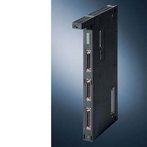
The optional EXM 438-1 input/output expansion module permits direct exchange of signals between the FM 458-1 DP basic module and the installation. The EXM 438-1 is able to record and convert the signals so rapidly that an up-to-date value is available for the FM 458-1 DP in every cycle (from 100 µs).
Обзор
- Optional plug-in expansion module for the FM 458-1 DP basic module
- For input and output of time-critical signals
- With digital and analog inputs/outputs
- Incremental and absolute value encoders can be connected
- 4 high-resolution analog outputs
- Fan-free operation up to 40°C
Дизайн
- 5 analog inputs
- 4 analog outputs 12 bit
- 4 analog outputs 16 bit
- 16 digital inputs
- 8 digital outputs
- 8 incremental encoders, with synchronization capability
- 4 absolute encoders
A fan is required at ambient temperatures above 40 °C.
Accessories
- SU13 interface module with SC63 cable for all signals without signal conversion.
- SB10, SB71, SU12 interface modules with SC62 cable for digital outputs
- SB10, SB61, SU12 interface modules with SC62 cable for digital inputs
Функции
Mode of operation
Coupling to FM 458-1 DP
The EXM 438-1 is connected directly to the FM 458-1 DP basic module via the internal bus. This makes the connection between the FM 458-1 DP and the I/O devices very fast. Only the power supply is obtained from the backplane bus of the SIMATIC rack, data transfer is not handled here. Access to the I/O is via configurable function blocks.
Configuration
Configuration instead of programming with CFC
The FM 458-1 DP is configured using the well-known software tools STEP 7 and CFC (Continuous Function Chart) which are also used to program the SIMATIC S7-400 controller.
CFC is an intuitive Windows-based program that is easy to learn. The CFC has been expanded to include the function blocks and the optimized operating system using the D7-SYS add-on software package.
For further information on D7-SYS, refer to "SIMATIC Software/Engineering Tools".
Технические данные
Order number | 6DD1607-0CA1 | |
|---|---|---|
EXM 438-1 I/O EXPENSION | ||
Supply voltage |
| |
Rated value (DC) | ||
| Yes | |
| Yes; to be set up externally | |
Input current |
| |
Current consumption, typ. | 1.5 A | |
Encoder supply |
| |
Type of output voltage | about 14 V (non-isolated) | |
Short-circuit protection | Yes; Electronic | |
Output current |
| |
| 100 mA | |
Hardware configuration |
| |
Slots |
| |
| 1 | |
Digital inputs |
| |
Number of digital inputs | 16 | |
Input voltage |
| |
| 24 V | |
| -1 to +6 V or input open | |
| +13 to +33V | |
Input current |
| |
| 0 mA | |
| 3 mA | |
Input delay (for rated value of input voltage) |
| |
for standard inputs |
| |
| 200 µs | |
Digital outputs |
| |
Number of digital outputs | 8 | |
Short-circuit protection | Yes; electronic/thermal | |
| 250 mA | |
Limitation of inductive shutdown voltage to | Supply voltage +1 V | |
Output voltage |
| |
| 3 V | |
| Supply voltage -2.5 V | |
Output current |
| |
| 50 mA | |
| 100 mA | |
| 20 µA | |
| 80% at 50 °C all outputs 50 mA | |
Output delay with resistive load |
| |
| 15 µs | |
Analog inputs |
| |
Number of analog inputs | 5; Differential inputs | |
Input ranges (rated values), voltages |
| |
| Yes; -10 V: +/-4 LSB; to +10 V: +/-4 LSB (1 LSB = 4.88 mV) | |
| 470 kΩ | |
Analog outputs |
| |
Number of analog outputs | 8; 4 outputs 16 bit; 4 outputs12 bit | |
Voltage output, short-circuit protection | Yes; relative to frame | |
Voltage output, short-circuit current, max. | 16 bits: 27 mA; 12 bits: 100 mA | |
Output ranges, voltage |
| |
| Yes | |
Analog value generation |
| |
Integration and conversion time/resolution per channel |
| |
| 4 AO: 16 bits, 4 AO: 12 bits, 5 AI: 12 bits | |
| 4 AO (16 bits): 2 µs; 4 AO (12 bits): 4 µs; 5 AI: 45 µs | |
Encoder |
| |
Number of connectable encoders, max. | 12; 8 incremental encoders (synchronizable), 4 absolute encoders | |
Connectable encoders |
| |
| Yes | |
| Yes | |
| Yes; Single or multiturn encoder with SSI (synchronous serial) or EnDat interface | |
Encoder signals, incremental encoder (symmetrical) |
| |
| 1) for tracks A and B (90° out of phase), poss. with zero pulse N; 2) for separate forward and backward track | |
| With 0 signal: -5 to 0 V; with 1 signal: +3 to +5 V; permissible input voltage range: differential voltage -5 to +5 V; max. input current: 15 mA (important: not limited on module side!) | |
Encoder signals, incremental encoder (asymmetrical) |
| |
| Track A and B (phase-shifted by 90 degrees), possibly with zero pulse N | |
| with 0 signal: -30 to +4 V (at 15 mA load); with 1 signal: +8 to 30 V (at 15 mA load); permissible input voltage range: differential voltage -30 to +30 V | |
Encoder signals, absolute encoder (SSI) |
| |
| 5 V acc. to RS 422 | |
| Dual-, Gray-, Gray-Excess-Code | |
| 2 MHz; 100 kHz to 2 MHz (depending on cable length) | |
Errors/accuracies |
| |
Linearity error (relative to output range), (+/-) | (+/- 1 LSB ) | |
Potential separation |
| |
Potential separation digital inputs |
| |
| No | |
Potential separation digital outputs |
| |
| No | |
Potential separation analog inputs |
| |
| No | |
Potential separation analog outputs |
| |
| No | |
Weights |
| |
Weight, approx. | 1 kg | |


 Ответ от производителя может занять до 5 дней и более.

