SIPLUS fail-safe customized modules Siemens
Область применения
The fail-safe modules of ET 200SP can be used to implement the safety-related application requirements as an integral part of the overall automation. The safety functions required for fail-safe operation are integrated in the modules. Communication to fail-safe SIMATIC S7 CPUs is performed by means of PROFIsafe. The modules can be operated both in centralized and distributed configurations.
Обзор
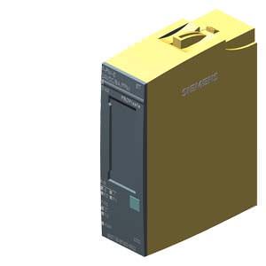
Digital fail-safe power module:·
F-PM-E PPM 24 V DC/8 A for BU type C0, color code CC52
Other properties:
- Certified up to SIL 3 (IEC 61508), PL e (ISO 13849)
- Safety-related shutdown of output modules within the potential group of the F-PM-E
- Two fail-safe digital inputs, for reading of sensor information (1 or 2 channels)
- One fail-safe digital output onboard (ppm switching, up to 2 A, up to SIL 3/PL e)
- Fail-safe digital output and potential supply pp or pm switching can be parameterized
- Parameterizable onboard evaluation of the fail-safe inputs for control of the fail-safe digital outputs and of the potential group
- Digital standard output modules can be shut down up to PL d (ISO 13849) and SIL 2 (IEC61508) (up to 8 A).
- Can be plugged into type C0 BaseUnits (BU) with automatic coding
- LED display for error, operation, supply voltage and status
- Clear labeling on front of module
- Plain text identification of the module type and function class
- 2D matrix code (order and serial number)
- Connection diagram
- Color coding of the module type DI: White
- Hardware and firmware version
- Color code CC for module-specific color coding of the potentials at the terminals of the BU
- Complete article No.
- Optional labeling accessories
- Labeling strips
- Reference identification label
- Optional module-specific color identification of the terminals according to the color code CC
- Optional system-integrated shield connection
- The modules support PROFIsafe in both PROFIBUS and PROFINET configurations. They can be used with all fail-safe SIMATIC S7 CPUs.
Note:
SIPLUS extreme products are based on SIMATIC standard products. The contents listed here were adopted from the respective standard products. SIPLUS extreme specific information was added.
Дизайн
Usable BaseUnits
For a single- or multi-conductor connection, BaseUnits with an appropriate number of terminals are available.
A light BaseUnit opens a new load group. The power supply to the sensors must be fed via this BU. The first BU next to the interface module must always be a light BU.
A dark BaseUnit forwards the power supply of the adjacent light BaseUnit on the left via self-assembling voltage buses. A new infeed is therefore only required on the next light BaseUnit to the right.
All variants that correspond to the BU type of the I/O module can be used as BaseUnits.
Color identification of the terminals
The potentials at the terminals of the BaseUnit are defined by the I/O module. Optionally, the potentials of the terminals can be identified by module-specific color-coding labels to prevent wiring errors. The color-coded label that matches the respective I/O module is defined by the color code CCxx of the I/O module. This color code is also printed on the front of the module.
In BaseUnits with the 10 internally jumpered AUX terminals, these can also be identified with color coding labels. For the 10 AUX terminals, color-coding labels are available in red, blue, and yellow/green.
System-integrated shielded connection
For the connection of cable shields that is both space-saving as well as optimized in terms of EMC, a shield connection is available that is quick and easy to mount. This consists of one shield connection element that can be plugged onto the BaseUnit and one shield terminal for each module. The low-impedance connection to the functional ground (DIN rail) is achieved without any additional wiring by the user.
Технические данные
Order number | 6AG1136-6PA00-2BC0 | |
|---|---|---|
SIPLUS ET 200SP F-PM-E 24VDC/8A PPM | ||
General information |
| |
Product type designation | F-PM-E PPM 24VDC | |
Product function |
| |
| Yes; I&M0 to I&M3 | |
Engineering with |
| |
| V12 | |
| V5.5 SP3 / - | |
| V2.3 | |
| V2.31 | |
Supply voltage |
| |
Type of supply voltage | 24 V DC | |
Rated value (DC) | 24 V | |
Reverse polarity protection | Yes | |
Output voltage |
| |
Type of output voltage | DC | |
Encoder supply |
| |
Number of outputs | 2 | |
Short-circuit protection | Yes; Electronic (response threshold 0.7 A to 2.1 A) | |
Output current |
| |
| 0.3 A | |
24 V encoder supply |
| |
| Yes; min. L+ (-1.5 V) | |
| Yes | |
| 600 mA; Summenstrom aller Geber | |
Digital inputs |
| |
Number of digital inputs | 2 | |
m/p-reading | Yes; p-reading | |
Input characteristic curve in accordance with IEC 61131, type 1 | Yes | |
Input voltage |
| |
| DC | |
| 24 V | |
| -30 to +5V | |
| +15 to +30V | |
Input current |
| |
| 3.7 mA | |
Input delay (for rated value of input voltage) |
| |
for standard inputs |
| |
| Yes | |
for counter/technological functions |
| |
| No | |
Cable length |
| |
| 1 000 m | |
| 500 m | |
Digital outputs |
| |
Number of digital outputs | 1 | |
Digital outputs, parameterizable | Yes | |
Short-circuit protection | Yes | |
Open-circuit detection | Yes | |
Overload protection | Yes | |
Limitation of inductive shutdown voltage to | max. 1.5 V | |
Switching capacity of the outputs |
| |
| 8 A | |
| 100 W | |
Load resistance range |
| |
| 3 Ω | |
| 2 000 Ω | |
Output voltage |
| |
| 24 V; L+ (-0.5 V) | |
Output current |
| |
| 8 A | |
| 1.5 mA; PP-switching: max. 1.5 mA; PM-switching: max. 1 mA | |
Switching frequency |
| |
| 10 Hz; Symmetrical | |
| 0.1 Hz; according to IEC 947-5-1, DC-13, symmetrical | |
| 4 Hz; Symmetrical | |
Total current of the outputs |
| |
| 8 A; Note derating data in the manual | |
| 8 A; Note derating data in the manual | |
Cable length |
| |
| 1 000 m | |
| 500 m | |
Interrupts/diagnostics/status information |
| |
Substitute values connectable | No | |
Alarms |
| |
| Yes | |
| No | |
Diagnostic messages |
| |
| Yes, "Alarms/diagnostic messages" section in the manual | |
Diagnostics indication LED |
| |
| Yes; Green LED | |
| Yes; Red LED | |
| Yes; green PWR LED | |
| Yes; Green LED | |
| Yes; Red LED | |
| Yes; green/red DIAG LED | |
Potential separation |
| |
Potential separation channels |
| |
| Yes | |
Isolation |
| |
Isolation tested with | 707 V DC (type test) | |
Standards, approvals, certificates |
| |
Suitable for safety functions | Yes | |
Highest safety class achievable in safety mode |
| |
| PLe | |
| SIL 3 | |
| < 2.00E-05 1/h | |
| < 1.00E-09 1/h | |
Ambient conditions |
| |
Extended ambient conditions |
| |
| Tmin ... Tmax at 1080 hPa ... 795 hPa (-1000 m ... +2000 m) | |
Relative humidity |
| |
| 100 %; RH incl. condensation/frost (no commissioning under condensation conditions) | |
Resistance |
| |
| Yes; Class 3B2 mold, fungus and dry rot spores (with the exception of fauna). The supplied connector covers must remain on the unused interfaces during operation! | |
| Yes; Class 3C4 (RH < 75%) incl. salt spray according to EN 60068-2-52 (degree of severity 3). The supplied connector covers must remain on the unused interfaces during operation! | |
| Yes; Class 3S4 incl. sand, dust. The supplied connector covers must remain on the unused interfaces during operation! | |
Dimensions |
| |
Width | 20 mm | |
Height | 72 mm | |
Depth | 55 mm | |
Weights |
| |
Weight, approx. | 70 g | |


 Ответ от производителя может занять до 5 дней и более.

