PoE power supplies for SCALANCE XM-400 managed Siemens

Обзор

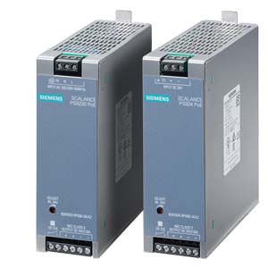
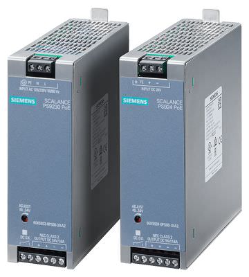
The SCALANCE PS924 PoE and SCALANCE PS9230 PoE power supplies have an output voltage of 54 V DC, which is especially required for PoE (Power-over-Ethernet) according to IEEE 802.3at. With PoE, both data and supply voltage is transmitted from the switch to the connected node via a single cable. Examples of typical nodes, so-called powered devices (PD), are WLAN Access Points, RFID readers, cameras, IP telephones etc.
- Both SCALANCE PS924 PoE and SCALANCE PS9230 PoE power supplies can be installed on standard mounting rails and are designed with IP20 degree of protection for use in control cabinets.
- They are especially suited for use in demanding environments for an operating temperature range from -40 °C to +70 °C.
- The SCALANCE PS924 PoE and SCALANCE PS9230 PoE power supplies are ideal for use in products from the SCALANCE X switch series.
- There are versions with 24 V DC or 120/230 V AC input voltages.
Product versions
SCALANCE PS924 PoE Power Supply
- Input voltage range from 19-29 V DC
- Output voltage 54 V DC
- 86 Woutput power
- Operating temperature from -40 °C to +70 °C
- IP20 degree of protection
SCALANCE PS9230 PoE Power Supply
- Input voltage range from 85-132/170-264 V AC
- Output voltage 54 V DC
- 86 Woutput power
- Operating temperature from -40 °C to +70 °C
- IP20 degree of protection
Дизайн
- Operating temperatures from -40 °C to +70 °C
- Compact design
- IP20 degree of protection
- For installation on 35 mm DIN mounting rails in control cabinet
- LED and signaling contact for status display (DC O.K.)
Интеграция
The SCALANCE PS924 and SCALANCE PS9230 power supplies are ideal for use with expansion module PE408PoE from the SCALANCE XM-400 product series. Two PS-900 power supplies can be connected for each PE408PoE. A PS-900 power supply provides 86 W and can therefore supply up to 4 ports on the PE408PoE. A maximum of 30 W are available at any one port.
Особенности

- Reduced cabling overhead since data line used transmit supply voltage as well (Power-over-Ethernet)
- High performance provided for connected PDs (up to 30 W)
- Flexibility regarding input voltage due to two available versions (24 V DC or 120/230 V AC)
- High availability, suitable for use in harsh environments (-40 °C to 70 °C)
- Space-saving due to compact construction and installation on the standard mounting rail
- Simple installation thanks to classification as current source with limit power (LPS / NEC Class 2)
Технические данные
Order number | 6GK5924-0PS00-1AA2 | 6GK5923-0PS00-3AA2 | |
|---|---|---|---|
Product type designation | Power Supply SCALANCE PS9230 PoE | Power Supply SCALANCE PS924 PoE | |
Type of current supply | Input: DC 24 V, Output: DC 54 V / 1,6 A, NEC CLASS 2 | Input: AC 120 / 230 V, Output: DC 54 V / 1,6 A, NEC CLASS 2 | |
Suitability for use | Power supply for PoE | Power supply for PoE | |
Electrical data Input |
|
| |
Voltage curve at input | DC | 1-phase AC | |
Supply voltage Rated value | 24 V | 230 V | |
Supply voltage Rated value | 19.2 ... 28.8 V | 85 ... 264 V | |
Consumed current at rated supply voltage maximum | 4.1 A | 1 A | |
Design of input wide range input | No | Yes | |
Overvoltage category | Category II | ||
Buffering time at rated output current in the event of power failure minimum | 5 ms | 50 ms | |
Line frequency |
|
| |
| Yes | ||
| Yes | ||
| 50 Hz | ||
| 60 Hz | ||
Line frequency | 47 ... 63 Hz | ||
Input current at rated input voltage 230 V Rated value | 1 A | ||
Current limitation of inrush current at 25 °C maximum | 10 A | 35 A | |
Fuse protection type at input | Fuse T 15A soldered | Fuse T 3.15A soldered | |
Electrical data Output |
|
| |
Voltage curve at output | Controlled, isolated DC voltage, adjustable from 48 V to 54 V | Controlled, isolated DC voltage, adjustable from 48 V to 54 V | |
Output voltage for DC Rated value | 54 V | 54 V | |
Display version for normal operation | LED green for DC ok | LED green for DC ok | |
Behavior of the output voltage when switching on | Overshoot of Ua < 2 % | Overshoot of Ua < 2 % | |
ON-delay time maximum | 1.5 s | 1.5 s | |
Voltage increase time of the output voltage maximum | 15 ms | 15 ms | |
Output current |
|
| |
| 1.6 A | 1.6 A | |
| 0 ... 1.8 A | 0 ... 1.8 A | |
Active power supplied typical | 86 W | 86 W | |
Product property Parallel switching of channels | No | No | |
Number of parallel-switched resources for increasing the power | 0 | 0 | |
Efficiency in percent | 86 % | 89 % | |
Active power loss | 14 W | 11 W | |
Electrical data Closed-loop control |
|
| |
Relative overall tolerance of the voltage | 1 % | 1 % | |
Residual ripple maximum | 0.05 V | 0.05 V | |
Voltage peak maximum | 0.2 V | 0.2 V | |
Relative control precision of the output voltage |
|
| |
| 0.2 % | 0.2 % | |
| 0.5 % | 0.5 % | |
| 0.5 % | 0.5 % | |
| 0.3 % | 0.3 % | |
Setting time |
|
| |
| 0.5 ms | 0.5 ms | |
| 0.5 ms | 0.5 ms | |
Electrical data Protection and monitoring |
|
| |
Design of the overvoltage protection at output | < 60 V | < 60 V | |
Response value current limitation typical | 1.7 A | 1.7 A | |
Property of the output Short-circuit proof | Yes | Yes | |
Design of short-circuit protection | Electronic shut...atic restart | Electronic shut...atic restart | |
Electrical data Safety |
|
| |
Galvanic isolation between entrance and outlet | Yes | Yes | |
Galvanic isolation | Safety extra-low output voltage Uout acc. to EN 60950-1 | Safety extra-low output voltage Uout acc. to EN 60950-1 | |
Operating resource protection class | Class III | Class I | |
Leakage current |
|
| |
| 3.5 mA | 3.5 mA | |
| 0 mA | 2 mA | |
Interfaces |
|
| |
Number of electrical connections |
|
| |
| 3 | 3 | |
| 2 | 2 | |
Type of electrical connection |
|
| |
| Screw terminal 0.5 - 2.5 mm² | Screw terminal 0.5 - 2.5 mm² | |
| FE / + / - screw terminal 0,5 - 2,5 mm² | PE / N / L scre...,5 - 2,5 mm² | |
| 2x + / 2x - , screw terminal 0.5 - 2.5 mm² | 2x + / 2x - , screw terminal 0.5 - 2.5 mm² | |
Signal-Inputs/outputs |
|
| |
Product component Signaling contact | Yes | Yes | |
Relay design | Normal open contact (N/O) | Normal open contact (N/O) | |
Operating voltage of the signaling contacts |
|
| |
| 24 V | 24 V | |
| 60 V | 60 V | |
Operating current of the signaling contacts |
|
| |
| 0.3 A | 0.3 A | |
| 0.3 A | 0.3 A | |
Design, dimensions and weight |
|
| |
Width | 42 mm | 42 mm | |
Height | 125 mm | 125 mm | |
Depth | 125 mm | 125 mm | |
Net weight | 0.5 kg | 0.5 kg | |
Product property of the enclosure housing for side-by-side mounting | Yes | Yes | |
Mounting type | |||
| No | No | |
| No | No | |
| Yes | Yes | |
| No | No | |
Permitted ambient conditions |
|
| |
Ambient temperature |
|
| |
| -40 ... +70 °C | -40 ... +70 °C | |
| -40 ... +85 °C | -40 ... +85 °C | |
| -40 ... +85 °C | -40 ... +85 °C | |
| Convection | Convection | |
Relative humidity at 25 °C without condensation during operation maximum | 95 % | 95 % | |
Protection class IP | IP20 | IP20 | |
Standards, specifications, approvals |
|
| |
Standard |
|
| |
| cULus-Listed (UL508, CSA C22.2 No. 107.1) | cULus-Listed (UL508, CSA C22.2 No. 107.1) | |
| EN 61000-6-4: 2007 | EN 61000-6-4: 2007 | |
| EN 61000-6-2 | EN 61000-6-2 | |
Certificate of suitability | EN 61000-6-4: 2007 | EN 61000-6-4: 2007 | |
| Yes | Yes | |
| Yes | Yes | |


 Ответ от производителя может занять до 5 дней и более.

