SITRANS AW210 WirelessHART adapter Siemens
Область применения
The WirelessHART adapter can be used in a number of different applications:
- Access to installed basis
Diagnostic information is obtained from existing wired HART devices thanks to the permanent electrical connection of a WirelessHART adapter and power from the 4 to 20 mA loop. This information is sent to central system-based asset management software such as SITRANS MDS. - Status monitoring of the plant
Wireless devices are mounted at critical points in the plant which are not usually connected to the control room due to difficult access or high wiring costs. Better data flow and diagnostics increase plant reliability, transparency and safety. - Process optimization
Temporary installation of a 4 to 20mA or standard HART device together with a SITRANS AW210 WirelessHART adapter allows easier, flexible monitoring and plant optimization at lower costs. SITRANS AW210 can also be usefully used where there is already an external power supply, or one is needed anyway. - Process monitoring
Measured values, for example from tanks or silos, are transmitted to a higher-level system at regular intervals together with the device status. SITRANS AW210 is particularly easy to use with 4-wire devices, as they have an external power supply.
Обзор

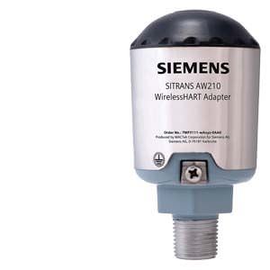
SITRANS AW210 WirelessHART adapter
The WirelessHART adapter SITRANS AW210 is a communication component which can integrate a wide range of field devices into a WirelessHART network. On the wireless communication side, the adapter supports the WirelessHART standard. HART and 4 to 20 mA field devices are connected on the field device side.
The WirelessHART adapter SITRANS AW210
- Supports the WirelessHART standard (HART V 7.1)
- Features an extremely high degree of security for wireless data transmission.
- Integrates a 4 to 20 mA field device into a WirelessHART network
- Integrates up to eight HART field devices (in multidrop mode) into a WirelessHART network
- Can be powered with the 4 to 20 mA loop or an external power supply
- Power management can be activated to minimize energy consumption
- Easy to configure with SIMATIC PDM, AMS, Handheld 475.
Дизайн
SITRANS AW210 WirelessHART Adapter consists of:
- An enclosure with a fitted aerial
- Electronics
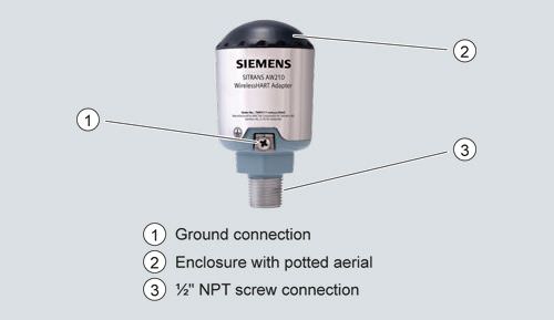
SITRANS AW210 Wireless-HART Adapter, assembly
The enclosure contains the potted electronics and the wireless module. The aerial is fitted at the top in the enclosure.
On the base of the enclosure is the connector with a ½" NPT female thread. Six cables run from this connector to connect the adapter.
Функции
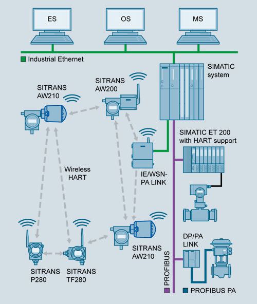
SITRANS AW210 WirelessHART Adapter, functional diagram
The measured values and diagnostic information from the connected field devices with HART communication are transmitted to the WirelessHART adapter over wired connections. The adapter transmits this information as wireless signals to the IE/WSN-PA link, the Siemens WirelessHART gateway. The measured values, all parameters and diagnostic information about the plant network can be accessed from this gateway.
If a field device with a 4 to 20 mA output signal is connected to the adapter, the current will be converted to a digital measured value and transmitted on the basis of a measuring range specified in SITRANS AW210.
Following configuration and integration into a WirelessHART network, each WirelessHART adapter is able to recognize its neighbors. It notes the strength of the wireless signal, synchronizes itself, receives network information and then establishes connections to its neighbors in the wireless network. A WirelessHART network organizes itself. Manual settings for organization are not required.
Two-wire and four-wire field devices can be connected to a WirelessHART adapter. Either up to 2 or up to 8 HART field devices can be connected to the adapter, depending on the selected product version. The adapter either has an external voltage supply or is loop-powered. The WirelessHART adapter can therefore also be connected in parallel to an existing installation consisting of a voltage supply and a HART field device.
Parameter assignment
SITRANS AW210 is configured via HART. Configuration can be carried out using handheld communicator 475 or, more conveniently, with a HART modem and the SIMATIC PDM configuration software.
Initial startup of the adapter is usually carried out via SIMATIC PDM and a HART modem or a handheld communicator. During initial startup, the network ID and join key are set in the adapter. These parameters are used to integrate the adapter into an existing WirelessHART network.
Following integration into the network, the adapter and HART devices connected can be conveniently operated via the WirelessHART network or locally, as detailed above.
Siemens HART field devices for the adapter
In principle, all HART devices certified by the HART Communication Foundation (HCF) can be operated with the SITRANS AW210 WirelessHART adapter. See http://www.siemens.com/automation/service&support for FAQ with the latest information on connectivity for Siemens field devices.
Note:
Siemens has only approved the Siemens HART field devices listed there for the adapter, and will only provide technical support for these devices.
Based on HART specifications, it is generally possible to connect devices that are not listed, however with the following restrictions:
- All warranties and liability will be excluded
- No technical support
Чертеж
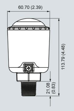
SITRANS AW210 WirelessHART adapter, dimensions in mm (inches)
Особенности
- "Intrinsically safe" or "Explosion proof"
- High quality and service life
- Extremely rugged enclosure
- No additional cabling required with loop power supply
- Subsequent integration of an installed field device with HART interface into maintenance and diagnostic systems if the control system does not feature the required communication mechanisms
- Proven HART devices can continue to be used for wireless communication without any limitations
- Field devices with a 4 to 20 mA interface (without HART) can also be connected
- Ideal addition to wired communication and to the range of system solutions in process automation
- Burst mode and event notification configuration for the adapter and connected field devices
Схема подключения
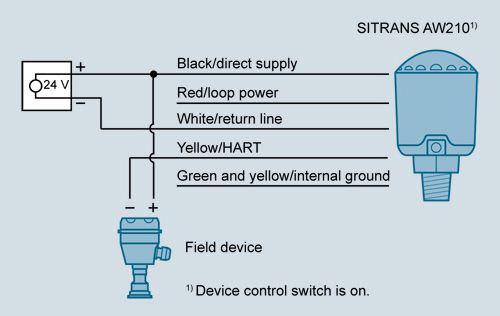
External 24 V DC power supply, connection of one device
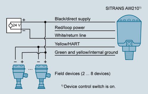
External 24 V DC power supply, connection of multiple devices
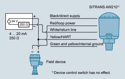
Loop power for connection of one 4 ... 20 mA HART device
Технические данные
Input | |
Point-to-point connection to a HART field device or | |
Communication |
|
Protocol | HART V7 (compatible with previous HART versions) |
Output | |
Communication | WirelessHART V7 |
Transmission frequency band | 2.4 … 2.4835 GHz (ISM band), 16-channel frequency hopping spread spectrum |
Range (under reference conditions) | Outside up to 235 m (771.00 ft) |
RF signal strength | 10 dBm |
Output signals | |
|
|
| Scaled or linearized process values |
|
|
Update time for output signals | You can set the update times separately for the adapter and the connected devices. The possible settings are:
|
Measuring accuracy | |
Max. measuring error (4 ... 20 mA circuit) | 1 % of measuring range, 40 … 85 °C (104 … 185 °F) |
Rated conditions | |
Location | Outside/inside |
Ambient conditions | |
| -40 ... +85 °C (-40 ... +185 °F) In hazardous areas up to 75 °C (167 °F) |
| -40 ... +85 °C (-40 ... +185 °F) |
Electromagnetic compatibility | To EN 301 489-17 and EN 300 328-1 |
Design | |
Weight | 0.46 kg (1.01 lb) |
Enclosure | |
| Enclosure: |
| ½" NPT female thread |
Degree of protection | IP68 |
Aerial | Potted in enclosure |
Auxiliary power | |
Power supply | Loop power 1 … DC 2.5 V, can be set by user in 0.5 V DC increments |
Loop-powered, operating current | DC 3.2 … 25 mA operating current; overvoltage, surge and reverse polarity protection |
Certificates and approvals | |
Wireless communication approvals |
|
Explosion protection | |
Intrinsic safe "i" gases and vapors | II 1G Ex ia IIC T*; IP68 |
Intrinsic safe dust | II 1 D Ex iaD 20 IP68 T95C; |
Non-sparking (zone 2) | II 3 G Ex nA nC IIC T* Gc; IP68 |
Explosion protection to FM for US Intrinsic safe, Non-sparking | IS/I,II,III/1/ABCDEFG/ NI/I/2/ABCD/ S/II,III/2/EFG/ I/0/AEx ia/IIC/ 20/AEx iaD/T95°C; I/2/AEx nA nC/IIC/ |
Explosion protection to FM for CA Intrinsic safe, Non-sparking | IS/I,II,III/1/ABCDEFG/ NI/I/2/ABCD/ S/II,III/2/EFG/ I/0/Ex ia/IIC/ I/2/Ex nA nC/IIC/ II/1/EFG Ta = -40 ... +85°C; IP68 |
Flameproof gases and vapors | II 2 G Ex d IIC T* Gb; IP68 |
Protection by enclosure dust | II 2 D Ex tb IIIC T95°C |
Explosion protection to FM for US Explosionproof, flameproof, gas, dust | XP/I/1/ABCD 21/AEx tb IIIC T95°C |
Explosion protection to FM for CA Explosionproof, flameproof, gas, dust | XP/I/1/ABCD |


 Ответ от производителя может занять до 5 дней и более.

