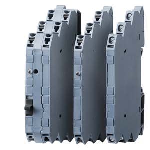
SIRIUS 3RS70 Signal Converters Siemens
Область применения
Signal converters are used in analog signal processing for
- Electrical separation
- Conversion of normalized and non-normalized signals
- Amplification and impedance adaptation
- Conversion to a frequency for processing by a digital input
- Overvoltage and EMC protection
- Short-circuit protection of the outputs
3RS7025 manual / automatic transformer
For special applications in which analog signals have to be simulated, or during plant commissioning when the actual process value is not yet available, the 3RS7025 devices feature an adjustable potentiometer for manual setpoint selection and a manual/automatic switch.
The potentiometer for the 3RS7025 devices is used to simulate analog output signals when the changeover switch is set to "Manual" and the control supply voltage is applied, without the need for an analog input signal, and the scale ranges from 0 % to 100 %.
Example: When it is set for an output of 4 mA to 20 mA, the 0 % scale value on the potentiometer represents an output current of 4 mA and the 100 % scale value represents an output current of 20 mA. In the "Auto" switch position, the output signal follows the input signal proportionally regardless of the potentiometer setting.

3RS70 signal converter, application example: Analog signal processing
Обзор

SIRIUS 3RS70 signal converters
Signal converters perform the coupling function for analog signals on both the input side and the output side. They are indispensable when processing analog values with electronic controls. Under harsh industrial conditions in particular, it is often necessary to transmit analog signals over long distances. Electrical separation is then needed as a result of the different power supplies. The resistance of the wiring causes potential differences and losses which must be prevented.
Electromagnetic disturbance and overvoltages can affect the signals on the input side in particular or even destroy the analog modules. All terminals of the 3RS70 signal converters are safe up to a voltage of 30 V DC and protected against reverse polarity. Short-circuit protection is an important function for the outputs above all.
The devices are EMC-tested according to
- IEC 61000-6-4 (generic standard for emitted interference)
- IEC 61000-6-2 (generic standard for interference immunity)
The analog signals comply with
- IEC 60381-1/2.
Note:
For the conversion tool, e.g. from 3RS17 to 3RS70 seewww.siemens.com/sirius/conversion-tool
Article No. scheme
Digit of the Article No. | 1. - 5. | 6. | 7. |
| 8. | 9. | 10. | 11. | 12. |
|---|---|---|---|---|---|---|---|---|---|
Signal converters | 3RS70 | ||||||||
Type of input signal | ❒ | ❒ | |||||||
Connection methods | ❒ | ||||||||
Type of output signal | ❒ | ||||||||
Design of the power supply | ❒ | ||||||||
Example | 3RS70 | 0 | 0 | – | 1 | A | E | 0 | 0 |
Note:
The Article No. scheme is presented here merely for information purposes and for better understanding of the logic behind the article numbers.
Особенности
- Narrow design
- Easy-to-set universal converters
- Converters with frequency output
- All ranges are fully calibrated
- Universal family of devices – the perfect solution for every application
- Integrated manual-automatic switch with a setpoint generator
- Outputs are short-circuit-proof
- Up to 30 V – protected against damage caused by wiring errors
Дальнейшая информация
Active signal converters
Active signal converters provide maximum flexibility for the application by the use of an external control supply voltage. Configuration with active signal converters is extremely easy because input and output resistances and voltage drops are compensated by the auxiliary supply. They support electrical separation as well as conversion from one signal type to another or reinforcement. The load of the measured value transmitter is negligible.
Passive signal converters
Passive signal converters do not require an external power supply. This advantage can only be used by current signals that are converted 1:1. Reinforcement or conversion is not possible. The converters are used for complete electrical separation of current signals and to protect the inputs and outputs. Passive signal converters do not operate reaction-free, i.e. any load on the output produces an equal load on the input signal. When the passive converter is to be used, the output power of the sensor and the input resistance of the analog input must be analyzed.
Calculation guide for passive converters
Important: Please note the following when using passive signal converters:
When the output is open, the input becomes high impedance, and the current-driving voltage of the measuring transducer UE must be sufficient to drive the maximum current of 20 mA over the passive converters with a voltage loss of UV = 2.8 V and the load RB.
This means:
UB ≥ UE = 2.8 V + 20 mA x RB

Distribution of the voltages in the case of passive signal converters
The following figure shows the input voltage UE as a function of the load RB taking into account the voltage loss UV. If the load is known, the y-axis shows the minimum voltage that has to be supplied by the current source in order to drive the maximum current of 20 mA over the passive signal converter and load.

Input voltage depending on the load at Ia = 20 mA
Load rating of the outputs
A maximum output load is specified for current signals. This resistance value specifies how large the input resistance of the next device connected in series can be as a result of the power of the converter.
For voltage signals, the maximum current that can be drawn from the output is the decisive factor.
3-way separation
For the 3-way separation, each circuit is electrically separated from the other circuits, i.e. input, output, and control supply voltage do not have equipotential bonding.

3-way separation


 Ответ от производителя может занять до 5 дней и более.

