Active Line Modules Siemens

Обзор
The self-commutated infeed/regenerative feedback units with IGBTs generate a regulated DC link voltage. This means that the connected Motor Modules are decoupled from the line voltage. Line voltage fluctuations within the permissible supply tolerances have no effect on the motor voltage.
If required, the Active Line Modules can also provide reactive power compensation.
Active Line Modules are designed for connection to grounded TN/TT and non-grounded IT supply systems.
Active Line Modules are always operated together with the associated Active Interface Modules. These include the necessary pre-charging circuit as well as a Clean Power Filter.
Дизайн
The Active Line Modules have the following interfaces as standard:
- 1 line supply connection
- 1 connection for the 24 V DC electronics power supply
- 1 DC link connection (DCP, DCN) for supplying the connected Motor Modules
- 1 DC link connection (DCPA, DCNA) for connecting a Braking Module
- 3 DRIVE-CLiQ sockets
- 1 temperature sensor input (KTY84-130, PTC or Pt100)
- 2 PE/protective conductor connections
The status of the Active Line Modules is indicated via two multicolor LEDs.
The scope of supply of the Active Line Modules includes:
- DRIVE-CLiQ cable for connecting to a CU320-2 or SIMOTION D4x5 Control Unit
- DRIVE-CLiQ cable to connect the Control Unit to the first Motor Module
Интеграция
The Active Line Modules communicate with the higher-level control module via DRIVE-CLiQ. The control module in this case can be a CU320-2 or a SIMOTION D Control Unit. An external 24 V DC power supply is required to operate the Active Line Modules.
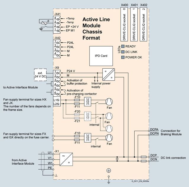
Connection example of an Active Line Module
Технические данные
General technical specifications
Electrical specifications | |
|---|---|
Line power factor | |
| 1.0 (factory setting) |
| 1.0 (factory setting) |
Efficiency | > 97.5 % (including AIM) |
DC link voltage | The DC link voltage is regulated and can be adjusted as a voltage decoupled from the line voltage. |
Radio interference suppression, standard | Category C3 according to EN 61800-3 (with Active Interface Module) |
Conformity | CE (EMC Directive No. 2004/108/EC and Low-Voltage Directive No. 2006/95/EC) |
Approvals, according to | cULus (only for drive units connected to line voltages 380 ... 480 V 3 AC and 500 ... 600 V 3 AC) |
Line voltage 380 … 480 V 3 AC | Active Line Modules | |||||
|---|---|---|---|---|---|---|
| 6SL3330-7TE32-1AA3 | 6SL3330-7TE32-6AA3 | 6SL3330-7TE33-8AA3 | 6SL3330-7TE35-0AA3 | 6SL3330-7TE36-1AA3 | |
Rated power | ||||||
| kW | 132 | 160 | 235 | 300 | 380 |
| kW | 115 | 145 | 210 | 270 | 335 |
| hp | 200 | 250 | 400 | 500 | 600 |
| hp | 150 | 200 | 300 | 400 | 500 |
DC link current | ||||||
| A | 235 | 291 | 425 | 549 | 678 |
| A | 209 | 259 | 378 | 489 | 603 |
| A | 352 | 436 | 637 | 823 | 1017 |
Infeed/regenerative feedback current | ||||||
| A | 210 | 260 | 380 | 490 | 605 |
| A | 315 | 390 | 570 | 735 | 907 |
Current demand | ||||||
| A | 1.1 | 1.1 | 1.35 | 1.35 | 1.4 |
| A | 0.63 | 1.13 | 1.8 | 1.8 | 3.6 |
DC link capacitance | ||||||
| μF | 4200 | 5200 | 7800 | 9600 | 12600 |
| μF | 41600 | 41600 | 76800 | 76800 | 134400 |
Power loss, max. 2) | ||||||
| kW | 2.2 | 2.7 | 3.9 | 4.8 | 6.2 |
| kW | 2.3 | 2.9 | 4.2 | 5.1 | 6.6 |
Cooling air requirement | m3/s | 0.17 | 0.23 | 0.36 | 0.36 | 0.78 |
Sound pressure level LpA 3) (1 m) at 50/60 Hz | dB | 64/67 | 64/67 | 69/73 | 69/73 | 70/73 |
Line supply connection U1, V1, W1 |
| M10 screw | M10 screw | M10 screw | M10 screw | 2 × M12 screw |
| mm2 | 2 × 185 | 2 × 185 | 2 × 240 | 2 × 240 | 4 × 240 |
DC link connection DCP, DCN |
| M10 screw | M10 screw | M10 screw | M10 screw | 4 × hole for M12 |
| mm2 | 2 × 185 | 2 × 185 | 2 × 240 | 2 × 240 | Busbar |
PE1/GND connection |
| M10 screw | M10 screw | M10 screw | M10 screw | M12 screw |
| mm2 | 2 × 185 | 2 × 185 | 2 × 240 | 2 × 240 | 240 |
PE2/GND connection |
| M10 screw | M10 screw | M10 screw | M10 screw | 2 × M12 screw |
| mm2 | 2 × 185 | 2 × 185 | 2 × 240 | 2 × 240 | 2 × 240 |
Cable length, max. 4) | ||||||
| m | 2700 | 2700 | 2700 | 2700 | 3900 |
| m | 4050 | 4050 | 4050 | 4050 | 5850 |
Degree of protection |
| IP20 | IP20 | IP20 | IP20 | IP00 |
Dimensions | ||||||
| mm | 326 | 326 | 326 | 326 | 503 |
| mm | 1400 | 1400 | 1533 | 1533 | 1475 |
| mm | 356 | 356 | 545 | 545 | 540 |
Weight, approx. | kg | 95 | 95 | 136 | 136 | 290 |
Frame size |
| FX | FX | GX | GX | HX |
1) The base load current IH DC is the basis for a duty cycle of 150 % for 60 s or Imax DC for 5 s with a duty cycle duration of 300 s.
2) The specified power loss represents the maximum value at 100 % utilization. The value is lower under normal operating conditions.
3) Total sound pressure level of Active Interface Module and Active Line Module.
4) Sum of all motor cables and DC link. Longer cable lengths for specific configurations are available on request. For additional information, please refer to the SINAMICS Low Voltage Engineering Manual.
Line voltage 380 … 480 V 3 AC | Active Line Modules | |||||
|---|---|---|---|---|---|---|
| 6SL3330-7TE37-5AA3 | 6SL3330-7TE38-4AA3 | 6SL3330-7TE41-0AA3 | 6SL3330-7TE41-2AA3 | 6SL3330-7TE41-4AA3 | |
Rated power | ||||||
| kW | 450 | 500 | 630 | 800 | 900 |
| kW | 400 | 465 | 545 | 690 | 780 |
| hp | 600 | 700 | 900 | 1000 | 1250 |
| hp | 600 | 700 | 800 | 900 | 1000 |
DC link current | ||||||
| A | 835 | 940 | 1103 | 1412 | 1574 |
| A | 700 | 837 | 982 | 1255 | 1401 |
| A | 1252 | 1410 | 1654 | 2120 | 2361 |
Infeed/regenerative feedback current | ||||||
| A | 745 | 840 | 985 | 1260 | 1405 |
| A | 1117 | 1260 | 1477 | 1890 | 2107 |
Current demand | ||||||
| A | 1.4 | 1.4 | 1.5 | 1.7 | 1.7 |
| A | 3.6 | 3.6 | 5.4 | 5.4 | 5.4 |
DC link capacitance | ||||||
| μF | 15600 | 16800 | 18900 | 26100 | 28800 |
| μF | 134400 | 134400 | 230400 | 230400 | 230400 |
Power loss, max. 2) | ||||||
| kW | 7.3 | 7.7 | 10.1 | 12.1 | 13.3 |
| kW | 7.7 | 8.2 | 10.8 | 13 | 14.2 |
Cooling air requirement | m3/s | 0.78 | 0.78 | 1.08 | 1.08 | 1.08 |
Sound pressure level LpA 3) (1 m) at 50/60 Hz | dB | 70/73 | 70/73 | 71/73 | 71/73 | 71/73 |
Line supply connection U1, V1, W1 |
| 2 × M12 screw | 2 × M12 screw | 3 × M12 screw | 3 × M12 screw | 3 × M12 screw |
| mm2 | 4 × 240 | 4 × 240 | 6 × 240 | 6 × 240 | 6 × 240 |
DC link connection DCP, DCN |
| 4 × hole for M12 | 4 × hole for M12 | 4 × hole for M12 | 4 × hole for M12 | 4 × hole for M12 |
| mm2 | Busbar | Busbar | Busbar | Busbar | Busbar |
PE1/GND connection |
| M12 screw | M12 screw | M12 screw | M12 screw | M12 screw |
| mm2 | 240 | 240 | 240 | 240 | 240 |
PE2/GND connection |
| 2 × M12 screw | 2 × M12 screw | 3 × M12 screw | 3 × M12 screw | 3 × M12 screw |
| mm2 | 2 × 240 | 2 × 240 | 3 × 240 | 3 × 240 | 3 × 240 |
Cable length, max. 4) | ||||||
| m | 3900 | 3900 | 3900 | 3900 | 3900 |
| m | 5850 | 5850 | 5850 | 5850 | 5850 |
Degree of protection |
| IP00 | IP00 | IP00 | IP00 | IP00 |
Dimensions | ||||||
| mm | 503 | 503 | 704 | 704 | 704 |
| mm | 1475 | 1475 | 1480 | 1480 | 1480 |
| mm | 540 | 540 | 550 | 550 | 550 |
Weight, approx. | kg | 290 | 290 | 450 | 450 | 450 |
Frame size |
| HX | HX | JX | JX | JX |
1) he base load current IH DC is the basis for a duty cycle of 150 % for 60 s or Imax DC for 5 s with a duty cycle duration of 300 s.
2) The specified power loss represents the maximum value at 100 % utilization. The value is lower under normal operating conditions.
3) Total sound pressure level of Active Interface Module and Active Line Module.
4) Sum of all motor cables and DC link. Longer cable lengths for specific configurations are available on request. For additional information, please refer to the SINAMICS Low Voltage Engineering Manual.
Line voltage 500 … 690 V 3 AC | Active Line Modules | ||||
|---|---|---|---|---|---|
| 6SL3330-7TG35-8AA3 | 6SL3330-7TG37-4AA3 | 6SL3330-7TG41-0AA3 | 6SL3330-7TG41-3AA3 | |
Rated power | |||||
| kW | 560 | 800 | 1100 | 1400 |
| kW | 550 | 705 | 980 | 1215 |
| kW | 435 | 560 | 780 | 965 |
| kW | 400 | 510 | 710 | 880 |
| hp | 600 | 900 | 1250 | 1500 |
| hp | 450 | 600 | 1000 | 1250 |
DC link current | |||||
| A | 644 | 823 | 1148 | 1422 |
| A | 573 | 732 | 1022 | 1266 |
| A | 966 | 1234 | 1722 | 2133 |
Infeed/regenerative feedback current | |||||
| A | 575 | 735 | 1025 | 1270 |
| A | 862 | 1102 | 1537 | 1905 |
Current demand | |||||
| A | 1.4 | 1.5 | 1.7 | 1.7 |
| A | 3.0 | 4.4 | 4.4 | 4.4 |
| A | 2.1 | 3.1 | 3.1 | 3.1 |
DC link capacitance | |||||
| μF | 7400 | 11100 | 14400 | 19200 |
| μF | 59200 | 153600 | 153600 | 153600 |
Power loss, max. 2) | |||||
| kW | 6.8 | 10.2 | 13.6 | 16.5 |
| kW | 6.2 | 9.6 | 12.9 | 15.3 |
Cooling air requirement | m3/s | 0.78 | 1.08 | 1.08 | 1.08 |
Sound pressure level LpA 3) (1 m) at 50/60 Hz | dB | 70/73 | 71/73 | 71/73 | 71/73 |
Line supply connection U1, V1, W1 |
| 2 × M12 screw | 3 × M12 screw | 3 × M12 screw | 3 × M12 screw |
| mm2 | 4 × 240 | 6 × 240 | 6 × 240 | 6 × 240 |
DC link connection DCP, DCN |
| 4 × hole for M12 | 4 × hole for M12 | 4 × hole for M12 | 4 × hole for M12 |
| mm2 | Busbar | Busbar | Busbar | Busbar |
PE1/GND connection |
| M12 screw | M12 screw | M12 screw | M12 screw |
| mm2 | 240 | 240 | 240 | 240 |
PE2/GND connection |
| 2 × M12 screw | 3 × M12 screw | 3 × M12 screw | 3 × M12 screw |
| mm2 | 2 x 240 | 3 x 240 | 3 x 240 | 3 x 240 |
Cable length, max. 4) | |||||
| m | 2250 | 2250 | 2250 | 2250 |
| m | 3375 | 3375 | 3375 | 3375 |
Degree of protection |
| IP00 | IP00 | IP00 | IP00 |
Dimensions | |||||
| mm | 503 | 704 | 704 | 704 |
| mm | 1475 | 1480 | 1480 | 1480 |
| mm | 540 | 550 | 550 | 550 |
Weight, approx. | kg | 290 | 450 | 450 | 450 |
Frame size |
| HX | JX | JX | JX |
1) The base load current IH DC is the basis for a duty cycle of 150 % for 60 s or Imax DC for 5 s with a duty cycle duration of 300 s.
2) The specified power loss represents the maximum value at 100 % utilization. The value is lower under normal operating conditions.
3) Total sound pressure level of Active Interface Module and Active Line Module.
4) Sum of all motor cables and DC link. Longer cable lengths for specific configurations are available on request. For additional information, please refer to the SINAMICS Low Voltage Engineering Manual.


 Ответ от производителя может занять до 5 дней и более.

