Active Interface Modules Siemens
Обзор
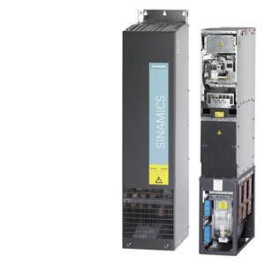
Active Interface Modules are used in conjunction with Active Line Modules. Active Interface Modules contain a Clean Power Filter with basic RI suppression, the pre-charging circuit for the Active Line Module, the line supply voltage sensing circuit and monitoring sensors. The bypass contactor is an integral component in frame sizes FI and GI, thereby making the module very compact. The bypass contactor must be provided separately for frame sizes HI and JI.
Line harmonics are largely suppressed by the Clean Power Filter.
Дизайн
The scope of supply of the Active Interface Modules includes:
- DRIVE-CLiQ cable for the connection between Active Interface Module and Active Line Module
- DRIVE-CLiQ cable for the connection between the Control Unit and first Motor Module
Интеграция
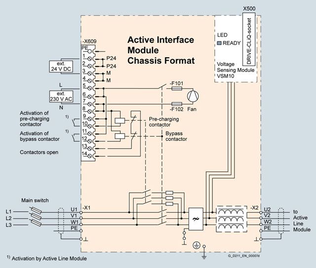
Connection example of an Active Interface Module with integrated bypass contactor (frame sizes FI and GI)
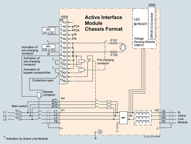
Connection example of an Active Interface Module with externally mounted bypass contactor (frame sizes HI and JI)
Технические данные
Line voltage 380 … 480 V 3 AC | Active Interface Modules | ||||
|---|---|---|---|---|---|
| 6SL3300-7TE32-6AA0 | 6SL3300-7TE33-8AA0 | 6SL3300-7TE35-0AA0 | ||
Suitable for Active Line Module | |||||
| kW | 132 | 160 | 235 | 300 |
|
| 6SL3330-7TE32-1AA3 | 6SL3330-7TE32-6AA3 | 6SL3330-7TE33-8AA3 | 6SL3330-7TE35-0AA3 |
|
| – | – | – | 6SL3335-7TE35-0AA3 |
Rated current | A | 210 | 260 | 380 | 490 |
Bypass contactor |
| included | included | included | included |
Current demand | |||||
| A | 0.17 | 0.17 | 0.17 | 0.17 |
| |||||
| A | 1.25 | 1.25 | 2.5 | 2.5 |
| A | 0.6 | 0.6 | 1.2 | 1.2 |
DC link capacitance of the drive line-up, max. 1) | μF | 41600 | 41600 | 76800 | 76800 |
Power loss, max. 2) | |||||
| kW | 2.1 | 2.2 | 3.0 | 3.9 |
| kW | 2.1 | 2.2 | 3.0 | 3.9 |
Cooling air requirement | m3/s | 0.24 | 0.24 | 0.47 | 0.47 |
Line supply/load connection L1, L2, L3 / U2, V2, W2 |
| M10 nut | M10 nut | M10 nut | M10 nut |
| mm2 | 2 × 185 | 2 × 185 | 2 × 185 | 2 × 185 |
PE/GND connection |
| M10 nut | M10 nut | M10 nut | M10 nut |
| mm2 | 2 × 185 | 2 × 185 | 2 × 185 | 2 × 185 |
Degree of protection |
| IP20 | IP20 | IP20 | IP20 |
Dimensions | |||||
| mm | 325 | 325 | 325 | 325 |
| mm | 1400 | 1400 | 1533 | 1533 |
| mm | 355 | 355 | 544 | 544 |
Weight, approx. | kg | 135 | 135 | 190 | 190 |
Frame size |
| FI | FI | GI | GI |
1)Information on higher capacities is included in the SINAMICS Low Voltage Engineering Manual.
2) The specified power loss represents the maximum value at 100 % utilization. The value is lower under normal operating conditions.
Line voltage 380 … 480 V 3 AC | Active Interface Modules | ||||
|---|---|---|---|---|---|
| 6SL3300-7TE38-4AA0 | 6SL3300-7TE41-4AA0 | |||
Suitable for Active Line Module | |||||
| kW | 380 | 450/500 | 630 | 800/900 |
|
| 6SL3330-7TE36-1AA3 | 6SL3330-7TE37-5AA3 | 6SL3330-7TE41-0AA3 | 6SL3330-7TE41-2AA3 |
|
| – | 6SL3335-7TE38-4AA3 | – | – |
Rated current | A | 605 | 840 | 985 | 1405 |
Bypass contactor |
| 3RT1476-6AP36 | 3WL1110-2BB34-4AN2-Z | 3WL1112-2BB34-4AN2-Z | 3WL1116-2BB34-4AN2-Z |
Current demand | |||||
| A | 0.17 | 0.17 | 0.17 | 0.17 |
| |||||
| A | 9.9 | 9.9 | 10.5 | 10.5 |
| A | 4.6 | 4.6 | 4.9 | 4.9 |
DC link capacitance of the drive line-up, max. 1) | μF | 134400 | 134400 | 230400 | 230400 |
Power loss, max. 2) | |||||
| kW | 5.5 | 6.1 | 7.5 | 8.5 |
| kW | 5.5 | 6.1 | 7.5 | 8.5 |
Cooling air requirement | m3/s | 0.4 | 0.4 | 0.4 | 0.4 |
Line supply/load connection L1, L2, L3 / U2, V2, W2 |
| 4 × hole for M12 | 4 × hole for M12 | 3 × hole for M12 | 3 × hole for M12 |
| mm2 | 4 × 240 | 4 × 240 | 6 × 240 | 6 × 240 |
PE/GND connection |
| 2 × M12 nut | 2 × M12 nut | 4 × M12 nut | 4 × M12 nut |
| mm2 | 2 × 240 | 2 × 240 | 4 × 240 | 4 × 240 |
Degree of protection |
| IP00 | IP00 | IP00 | IP00 |
Dimensions | |||||
| mm | 305 | 305 | 505 | 505 |
| mm | 1750 | 1750 | 1750 | 1750 |
| mm | 544 | 544 | 544 | 544 |
Weight, approx. | kg | 390 | 390 | 620 | 620 |
Frame size |
| HI | HI | JI | JI |
1)Information on higher capacities is included in the SINAMICS Low Voltage Engineering Manual.
2) The specified power loss represents the maximum value at 100 % utilization. The value is lower under normal operating conditions.
Line voltage 500 … 690 V 3 AC | Active Interface Modules | ||||
|---|---|---|---|---|---|
| 6SL3300-7TG35-8AA0 | 6SL3300-7TG37-4AA0 | 6SL3300-7TG41-3AA0 | ||
Suitable for Active Line Module | |||||
| kW | 560 | 800 | 1100 | 1400 |
|
| 6SL3330-7TG35-8AA3 | 6SL3330-7TG37-4AA3 | 6SL3330-7TG41-0AA3 | 6SL3330-7TG41-3AA3 |
|
| 6SL3335-7TG35-8AA3 | – | – | 6SL3335-7TG41-3AA3 |
Rated current | A | 575 | 735 | 1025 | 1270 |
Bypass contactor |
| 3RT1476-6AP36 | 3RT1476-6AP36 (3 units) | 3WL1212-4BB34-4AN2-Z | 3WL1216-4BB34-4AN2-Z |
Current demand | |||||
| A | 0.17 | 0.17 | 0.17 | 0.17 |
| |||||
| A | 9.9 | 10.5 | 10.5 | 10.5 |
| A | 4.6 | 4.9 | 4.9 | 4.9 |
DC link capacitance of the drive line-up, max. 1) | μF | 59200 | 153600 | 153600 | 153600 |
Power loss, max. 2) | |||||
| kW | 6.8 | 9.0 | 9.2 | 9.6 |
| kW | 6.8 | 9.0 | 9.2 | 9.6 |
Cooling air requirement | m3/s | 0.4 | 0.4 | 0.4 | 0.4 |
Line supply/load connection L1, L2, L3 / U2, V2, W2 |
| 4 × hole for M12 | 3 × hole for M12 | 3 × hole for M12 | 3 × hole for M12 |
| mm2 | 4 × 240 | 6 × 240 | 6 × 240 | 6 × 240 |
PE/GND connection |
| 2 × M12 nut | 4 × M12 nut | 4 × M12 nut | 4 × M12 nut |
| mm2 | 2 × 240 | 4 × 240 | 4 × 240 | 4 × 240 |
Degree of protection |
| IP00 | IP00 | IP00 | IP00 |
Dimensions | |||||
| mm | 305 | 505 | 505 | 505 |
| mm | 1750 | 1750 | 1750 | 1750 |
| mm | 544 | 544 | 544 | 544 |
Weight, approx. | kg | 390 | 620 | 620 | 620 |
Frame size |
| HI | JI | JI | JI |
1)Information on higher capacities is included in the SINAMICS Low Voltage Engineering Manual.
2) The specified power loss represents the maximum value at 100 % utilization. The value is lower under normal operating conditions.


 Ответ от производителя может занять до 5 дней и более.

