Motor Modules Siemens

Обзор
A Motor Module comprises a self-commutated inverter with IGBTs. It generates a variable voltage with variable frequency from the DC link voltage that feeds the connected motor.
Several Motor Modules can be interconnected through a common DC bus. This makes it possible to exchange energy between the Motor Modules. This means that if a Motor Module is in the generator mode, this energy can be used by another Motor Module operating in the motor mode.
Motor Modules are controlled by a Control Unit.
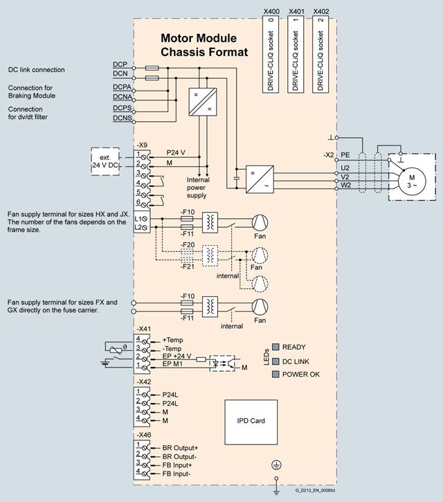
Дизайн
The Motor Modules in the chassis format have the following interfaces as standard:
- 1 DC link connection (DCP, DCN) for connecting to the supply DC busbar
- 1 DC link connection (DCPA, DCNA) for connecting a Braking Module
- 1 DC link connection (DCPS, DCNS) to connect a dv/dt filter
- 1 connection for the 24 V DC electronics power supply
- 3 DRIVE-CLiQ sockets
- 1 motor connection
- 1 connection for Safety Integrated
- 1 temperature sensor input (KTY84-130, PTC or Pt100)
- 2 PE/protective conductor connections
The status of the Motor Modules is indicated via two multi-color LEDs.
The scope of supply of the Motor Modules includes:
- DRIVE-CLiQ cable to connect to the CU320-2 or SIMOTION D4x5 Control Unit
- DRIVE-CLiQ cable for connection to the next Motor Module
Интеграция
The Motor Modules communicate with the higher-level control module via DRIVE-CLiQ. The control module in this case can be a CU320-2 or a SIMOTION D Control Unit.
Connection example of a Motor Module
Технические данные
General technical specifications
Electrical specifications | |
|---|---|
Efficiency | > 98.5 % |
DC link voltage (up to 2000 m above sea level) | 510 ... 720 V DC (line supply voltage 380 ... 480 V 3 AC) or |
Output frequency 1) | |
| 0 … 650 Hz |
| 0 … 600 Hz |
| 0 … 600 Hz |
Conformity | CE (EMC Directive No. 2004/108/EC and Low-Voltage Directive No. 2006/95/EC) |
Approvals, according to | cULus (only for drive units connected to line voltages 380 ... 480 V 3 AC and 500 ... 600 V 3 AC) |
Safety Integrated | Safety Integrity Level 2 (SIL2) acc. to IEC 61508, Performance Level d (PLd) acc. to EN ISO 13849-1 and Control Category 3 acc. to EN ISO 13849-1 (previously EN 954-1). |
1) Please note:
- The correlation between the maximum output frequency, pulse frequency and current derating. Higher output frequencies for specific configurations are available on request.
- The correlation between the minimum output frequency and permissible output current (current derating).
Information is provided in the SINAMICS Low Voltage Engineering Manual.
Line voltage 380 … 480 V 3 AC | Motor Modules | |||||
|---|---|---|---|---|---|---|
| 6SL3320-1TE32-1AA3 | 6SL3320-1TE32-6AA3 | 6SL3320-1TE33-1AA3 | 6SL3320-1TE33-8AA3 | 6SL3320-1TE35-0AA3 | |
Type rating | ||||||
| kW | 110 | 132 | 160 | 200 | 250 |
| kW | 90 | 110 | 132 | 160 | 200 |
| hp | 150 | 200 | 250 | 300 | 400 |
| hp | 150 | 200 | 200 | 250 | 350 |
Output current | ||||||
| A | 210 | 260 | 310 | 380 | 490 |
| A | 205 | 250 | 302 | 370 | 477 |
| A | 178 | 233 | 277 | 340 | 438 |
| A | 307 | 375 | 453 | 555 | 715 |
DC link current | ||||||
| ||||||
| A | 252 | 312 | 372 | 456 | 588 |
| A | 227 | 281 | 335 | 411 | 529 |
| ||||||
| A | 245 | 304 | 362 | 444 | 573 |
| A | 221 | 273 | 326 | 400 | 515 |
| ||||||
| A | 224 | 277 | 331 | 405 | 523 |
| A | 202 | 250 | 298 | 365 | 470 |
Current demand | ||||||
| A | 0.8 | 0.8 | 0.9 | 0.9 | 0.9 |
| A | 0.63 | 1.13 | 1.8 | 1.8 | 1.8 |
DC link capacitance | μF | 4200 | 5200 | 6300 | 7800 | 9600 |
Pulse frequency 5) | ||||||
| kHz | 2 | 2 | 2 | 2 | 2 |
| ||||||
| kHz | 2 | 2 | 2 | 2 | 2 |
| kHz | 8 | 8 | 8 | 8 | 8 |
Power loss, max. 6) | ||||||
| kW | 1.86 | 2.5 | 2.96 | 3.67 | 4.28 |
| kW | 1.94 | 2.6 | 3.1 | 3.8 | 4.5 |
Cooling air requirement | m3/s | 0.17 | 0.23 | 0.36 | 0.36 | 0.36 |
Sound pressure level LpA (1 m) at 50/60 Hz | dB | 64/67 | 64/67 | 69/73 | 69/73 | 69/73 |
DC link connection DCP, DCN |
| M10 screw | M10 screw | M10 screw | M10 screw | M10 screw |
| mm2 | 2 × 185 | 2 × 185 | 2 × 240 | 2 × 240 | 2 × 240 |
Motor connection U2, V2, W2 |
| M10 screw | M10 screw | M10 screw | M10 screw | M10 screw |
| mm2 | 2 × 185 | 2 × 185 | 2 × 240 | 2 × 240 | 2 × 240 |
Cable length, max. 7) | ||||||
| m | 300 | 300 | 300 | 300 | 300 |
| m | 450 | 450 | 450 | 450 | 450 |
PE1/GND connection |
| M10 screw | M10 screw | M10 screw | M10 screw | M10 screw |
| mm2 | 2 × 185 | 2 × 185 | 2 × 240 | 2 × 240 | 2 × 240 |
PE2/GND connection |
| M10 screw | M10 screw | M10 screw | M10 screw | M10 screw |
| mm2 | 2 × 185 | 2 × 185 | 2 × 240 | 2 × 240 | 2 × 240 |
Degree of protection |
| IP20 | IP20 | IP20 | IP20 | IP20 |
Dimensions | ||||||
| mm | 326 | 326 | 326 | 326 | 326 |
| mm | 1400 | 1400 | 1533 | 1533 | 1533 |
| mm | 356 | 356 | 545 | 545 | 545 |
Weight, approx. | kg | 95 | 95 | 136 | 136 | 136 |
Frame size |
| FX | FX | GX | GX | GX |
1) Rated power of a typ. 6-pole standard induction motor based on IL or IH with 400 V 3 AC 50 Hz.
2) Rated power of a typ. 6-pole standard induction motor based on IL or IH with 460 V 3 AC 60 Hz.
3) The base load current IL is the basis for a duty cycle of 110 % for 60 s or 150 % for 10 s with a duty cycle duration of 300 s.
4) The base load current IH is the basis for a duty cycle of 150 % for 60 s or 160 % for 10 s with a duty cycle duration of 300 s.
5)Information regarding the correlation between the pulse frequency and maximum output current/output frequency is provided in the SINAMICS Low Voltage Engineering Manual.
6) The specified power loss represents the maximum value at 100 % utilization. The value is lower under normal operating conditions.
7) Sum of all motor cables and DC link. Longer cable lengths for specific configurations are available on request. For additional information, please refer to the SINAMICS Low Voltage Engineering Manual.
Line voltage 380 … 480 V 3 AC | Motor Modules | |||
|---|---|---|---|---|
| 6SL3320-1TE36-1AA3 | 6SL3320-1TE37-5AA3 | 6SL3320-1TE38-4AA3 | |
Type rating | ||||
| kW | 315 | 400 | 450 |
| kW | 250 | 315 | 400 |
| hp | 500 | 600 | 700 |
| hp | 350 | 450 | 600 |
Output current | ||||
| A | 605 | 745 | 840 |
| A | 590 | 725 | 820 |
| A | 460 | 570 | 700 |
| A | 885 | 1087 | 1230 |
DC link current | ||||
| ||||
| A | 726 | 894 | 1008 |
| A | 653 | 805 | 907 |
| ||||
| A | 707 | 871 | 982 |
| A | 636 | 784 | 884 |
| ||||
| A | 646 | 795 | 897 |
| A | 581 | 716 | 807 |
Current demand | ||||
| A | 1.0 | 1.0 | 1.0 |
| A | 3.6 | 3.6 | 3.6 |
DC link capacitance | μF | 12600 | 15600 | 16800 |
Pulse frequency | ||||
| kHz | 1.25 | 1.25 | 1.25 |
| ||||
| kHz | 1.25 | 1.25 | 1.25 |
| kHz | 7.5 | 7.5 | 7.5 |
Power loss, max. 6) | ||||
| kW | 5.84 | 6.68 | 7.15 |
| kW | 6.3 | 7.3 | 7.8 |
Cooling air requirement | m3/s | 0.78 | 0.78 | 0.78 |
Sound pressure level LpA (1 m) at 50/60 Hz | dB | 70/73 | 70/73 | 70/73 |
DC link connection DCP, DCN |
| 4 × hole for M10 | 4 × hole for M10 | 4 × hole for M10 |
Motor connection U2, V2, W2 |
| 2 × M12 screw | 2 × M12 screw | 2 × M12 screw |
| mm2 | 4 × 240 | 4 × 240 | 4 × 240 |
Cable length, max. 7) | ||||
| m | 300 | 300 | 300 |
| m | 450 | 450 | 450 |
PE1/GND connection |
| M12 screw | M12 screw | M12 screw |
| mm2 | 240 | 240 | 240 |
PE2/GND connection |
| 2 × M12 screw | 2 × M12 screw | 2 × M12 screw |
| mm2 | 2 × 240 | 2 × 240 | 2 × 240 |
Degree of protection |
| IP00 | IP00 | IP00 |
Dimensions | ||||
| mm | 503 | 503 | 503 |
| mm | 1475 | 1475 | 1475 |
| mm | 547 | 547 | 547 |
Weight, approx. | kg | 290 | 290 | 290 |
Frame size |
| HX | HX | HX |
1) Rated power of a typ. 6-pole standard induction motor based on IL or IH with 400 V 3 AC 50 Hz.
2) Rated power of a typ. 6-pole standard induction motor based on IL or IH with 460 V 3 AC 60 Hz.
3) The base load current IL is the basis for a duty cycle of 110 % for 60 s or 150 % for 10 s with a duty cycle duration of 300 s.
4) The base load current IH is the basis for a duty cycle of 150 % for 60 s or 160 % for 10 s with a duty cycle duration of 300 s.
5)Information regarding the correlation between the pulse frequency and maximum output current/output frequency is provided in the SINAMICS Low Voltage Engineering Manual.
6) The specified power loss represents the maximum value at 100 % utilization. The value is lower under normal operating conditions.
7) Sum of all motor cables and DC link. Longer cable lengths for specific configurations are available on request. For additional information, please refer to the SINAMICS Low Voltage Engineering Manual.
Line voltage 380 … 480 V 3 AC | Motor Modules | |||
|---|---|---|---|---|
| 6SL3320-1TE41-0AA3 | 6SL3320-1TE41-2AA3 | 6SL3320-1TE41-4AA3 | |
Type rating | ||||
| kW | 560 | 710 | 800 |
| kW | 450 | 560 | 710 |
| hp | 800 | 1000 | 1150 |
| hp | 700 | 900 | 1000 |
Output current | ||||
| A | 985 | 1260 | 1405 |
| A | 960 | 1230 | 1370 |
| A | 860 | 1127 | 1257 |
| A | 1440 | 1845 | 2055 |
DC link current | ||||
| ||||
| A | 1182 | 1512 | 1686 |
| A | 1064 | 1361 | 1517 |
| ||||
| A | 1152 | 1474 | 1643 |
| A | 1037 | 1326 | 1479 |
| ||||
| A | 1051 | 1345 | 1500 |
| A | 946 | 1211 | 1350 |
Current demand | ||||
| A | 1.25 | 1.40 | 1.40 |
| A | 5.4 | 5.4 | 5.4 |
DC link capacitance | μF | 18900 | 26100 | 28800 |
Pulse frequency 5) | ||||
| kHz | 1.25 | 1.25 | 1.25 |
| ||||
| kHz | 1.25 | 1.25 | 1.25 |
| kHz | 7.5 | 7.5 | 7.5 |
Power loss, max. 6) | ||||
| kW | 9.5 | 11.1 | 12.0 |
| kW | 10.2 | 12.0 | 13.0 |
Cooling air requirement | m3/s | 1.1 | 1.1 | 1.1 |
Sound pressure level LpA (1 m) at 50/60 Hz | dB | 71/73 | 71/73 | 71/73 |
DC link connection DCP, DCN |
| 4 × hole for M10 | 4 × hole for M10 | 4 × hole for M10 |
Motor connection U2, V2, W2 |
| 3 × M12 screw | 3 × M12 screw | 3 × M12 screw |
| mm2 | 6 × 240 | 6 × 240 | 6 × 240 |
Cable length, max. 7) | ||||
| m | 300 | 300 | 300 |
| m | 450 | 450 | 450 |
PE1/GND connection |
| M12 screw | M12 screw | M12 screw |
| mm2 | 240 | 240 | 240 |
PE2/GND connection |
| 3 × M12 screw | 3 × M12 screw | 3 × M12 screw |
| mm2 | 3 × 240 | 3 × 240 | 3 × 240 |
Degree of protection | IP00 | IP00 | IP00 | |
Dimensions |
| |||
| mm | 704 | 704 | 704 |
| mm | 1475 | 1475 | 1475 |
| mm | 549 | 549 | 549 |
Weight, approx. | kg | 450 | 450 | 450 |
Frame size |
| JX | JX | JX |
1) Rated power of a typ. 6-pole standard induction motor based on IL or IH with 400 V 3 AC 50 Hz.
2) Rated power of a typ. 6-pole standard induction motor based on IL or IH with 460 V 3 AC 60 Hz.
3) The base load current IL is the basis for a duty cycle of 110 % for 60 s or 150 % for 10 s with a duty cycle duration of 300 s.
4) The base load current IH is the basis for a duty cycle of 150 % for 60 s or 160 % for 10 s with a duty cycle duration of 300 s.
5)Information regarding the correlation between the pulse frequency and maximum output current/output frequency is provided in the SINAMICS Low Voltage Engineering Manual.
6) The specified power loss represents the maximum value at 100 % utilization. The value is lower under normal operating conditions.
7) Sum of all motor cables and DC link. Longer cable lengths for specific configurations are available on request. For additional information, please refer to the SINAMICS Low Voltage Engineering Manual.
Line voltage 500 … 690 V 3 AC | Moto Запрос коммерческого предложения× Сообщение отправлено× В ближайшее время сообщение будет обработано. Письмо с номером обращения отправлено на Ваш почтовый ящик. Спасибо за то, что выбрали Первый ZIP! Что-то пошло не так...× К сожалению, наша система расценила Ваше сообщение как спам. Если это произошло по ошибке, пожалуйста, обратитесь к нам по электронной почте. Приносим извинения за возможные неудобства.  Вы отправляете нам запрос  Если у нас есть прайс-лист, мы отправляем Вам ответ в течение дня. А если у нас нет прайс-листа по запрошенным товарам?     Если у нас нет прайс-листа, мы отправляем запрос производителю.  Ответ от производителя может занять до 5 дней и более. Ответ от производителя может занять до 5 дней и более.  Запрос производителю мы отправляем только для конечных потребителей.  Торгующим организациям коммерческие предложения предоставляются только по прайсовым позициям: Siemens Beckhoff Pepperl+Fuchs Phoenix Contact PILZ Turck Leuze Electronic Endress+Hauser Murr Elektronik Schmersal | ||||
|---|---|---|---|---|---|