BaseUnits and I/O modules Siemens
Обзор
BaseUnits
- Type A0 BaseUnits with 16 process terminals
- Terminal box light
- Terminal box light, with 10 additional AUX terminals (internally jumpered)
- Terminal box dark
- Terminal box dark, with 10 additional AUX terminals (internally jumpered)
- Type A1 BaseUnits for analog modules for temperature detection with 16 process terminals
- Terminal box light
- Terminal box light, with 2 × 5 internally jumpered add-on terminals
- Terminal box dark
- Terminal box dark, with 2 × 5 internally jumpered add-on terminals
- Type B0 BaseUnit for digital output module with relays, terminal box dark; 12 process terminals and 4 internally jumpered AUX terminals
I/O modules
- Digital I/O modules
- Digital input modules, 8 or 16 channels
- Digital output modules, 4, 8 or 16 channels, including relay module
- Analog I/O modules
- Analog input modules, 2 or 4‑channel
- Analog output modules, 2 or 4‑channel
Supplementary material
- BU cover
- Labeling strips
- Reference ID labels
- Color-coding labels
- Shield connection
Дизайн
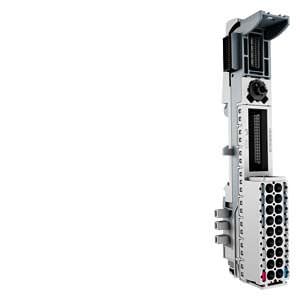
ET 200SP BaseUnit
BaseUnits
The I/O modules are plugged into BaseUnits (BU). BaseUnit versions suitable for this are those which correspond to the BU type (A0/A1/B0/D0) of the selected I/O module.
The BaseUnits provide electrical and mechanical connections between the I/O modules. To this end, the BaseUnits are mounted on a standard rail and latched into each other from the side.
The module slot also has a position for a coding element. This automatically codes the I/O module type when it is inserted for the first time, and prevents any different type of module from being inserted.
Each BaseUnit has a replaceable terminal box. In addition to the process terminals, this has two terminals (L+ and M) for the 24 V DC supply for the I/O modules and sensors. The plug-in terminals are designed to be space-saving and easy to fit.
BaseUnits are available with light or dark terminal boxes. BaseUnits with a light terminal block (light BUs) separate the self-assembling voltage buses (P1, P2, and AUX) from the adjacent module on the left and thus open up a new load group. The 24 V DC supply for the I/O modules and sensors of this load group (max. thermal continuous load 10 A) is connected to P1 (+) and P2 (-) via the terminals at the bottom with red and blue spring NC contacts.
BaseUnits with dark terminal box (dark BUs) are connected onto the right of a light BU. Contrary to the light BUs, they link the voltage buses P1, P2 and AUX to the adjacent module on the left and thus extend the voltage group. A new power supply is therefore only necessary at the next light BU.
Certain BaseUnits additionally have internally jumpered AUX terminals. Potentials of up to 24 V DC or protective earth (PE) conductors can be connected to the AUX rails.
The BaseUnits of type A1 which can be connected to analog modules for temperature detection enable recording of the terminal temperature using an integrated sensor for automatic temperature compensation for thermocouples. These BaseUnits are also available with 2 × 5 add-on terminals (internally jumpered).
Supplementary material for I/O modules and BaseUnits
BU cover
Unequipped BaseUnit slots reserved for later use can be protected by a BU cover. A 15 or 20 mm wide BU cover must be selected depending on the type of BaseUnit. It can be provided with a reference ID label.
Labeling strips
Appropriate light gray labeling strips for insertion in I/O modules are available in two different materials:
- Roll for thermal transfer roll printer with 500 labeling strips each
- Paper sheets for laser printer, A4 format, with 100 labeling strips each
Reference ID labels
The reference ID labels delivered as a package comprising 10 sheets with 16 strips each are used to identify bus adapters and BaseUnits as well as interface and I/O modules. The labels suitable for printing with commercially available thermal transfer printers are easy to insert into the corresponding module.
Color-coding labels
To prevent wiring faults, the potentials at the terminals of the BaseUnits can be coded using color-coded labels. The color-coded labels are simply attached to the terminal box. The following versions are available:
- Module-specific color-coded labels for process terminals. Selection is made depending on the color code (CCxx) printed on the front of the I/O module. The color code CC00 means that a color-coded label is not available for the process terminals of this I/O module.
- Color-coded labels for the 10 AUX terminals of BaseUnit type A0 in red, blue, and yellow/green.
- Color-coded labels for the 2 × 5 add-on terminals of the BaseUnit type A1 in red/blue.
- Color-coded labels for the 4 AUX terminals of BaseUnits type B0 in red, blue, and yellow/green.
Shield connection
A shield connection that is quick and easy to mount, comprising a shield connection element (can be plugged into the BaseUnit) and a shield terminal, permit the connection of cable shields that is both space-saving as well as optimized in terms of EMC. The shielded cable is fixed to the shield connecting element by means of the shield terminal. The low-impedance connection to the functional ground (standard mounting rail) does not require any additional wiring by the user.
The shield connection is supplied as a package containing 5 shield connection elements and 5 shield terminals.


 Ответ от производителя может занять до 5 дней и более.

