Line Connection Modules Siemens
Обзор
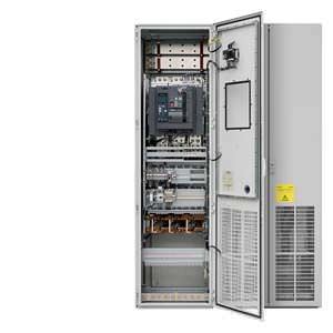
Line Connection Modules (LCM) contain the line-side infeed with main circuit breaker and fuse switch disconnector or circuit breaker and provide the connection between the plant power system and the Line Modules.
Line Connection Modules are available for the following voltages and currents:
Line voltage | Rated infeed/regenerative feedback current |
|---|---|
380 … 480 V 3 AC | 250 … 3200 A |
500 … 690 V 3 AC | 280 … 3200 A |
Дизайн
Different versions exist depending on the input current:
- Units ≤ 800 A include a main control switch with fuse switch disconnector
- Units > 800 A include a fixed-mounted circuit breaker (a withdrawable circuit breaker is optionally possible)
When Line Connection Modules are ordered, the type of Line Module used must be specified:
- for Basic Line Modules: Option L43
- for Smart Line Modules: Option L44
- for Active Line Modules: Option L42
When using a Basic Line Modules, a reactor is included in the scope of delivery, and when required, can be deselected (option L22).
For additional information, please refer to the SINAMICS Low Voltage Engineering Manual.
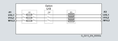
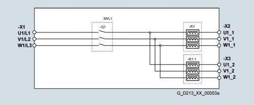
Connection example of a Line Connection Module for units ≤ 800 A
to connect to Basic Line Modules, option L43,
Option main contactor, order code L13
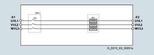
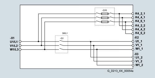
Example of connection of a Line Connection Module for units > 800 A, < 2000 A
to connect to the Basic Line Modules, option L43
For input currents ≥ 2000 A, additional options are available:
- Grounding switch upstream of main circuit breaker: Option L46
- Current transformer upstream of main circuit breaker: Option L41
- Grounding switch downstream of main circuit breaker: Option L47
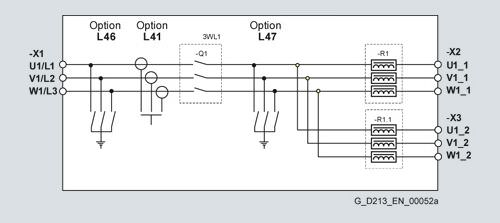
Example of connection of a Line Connection Module ≥ 2000 A
When Basic Line Modules that are fed via a common Line Connection Module are connected in parallel, line reactors are generally required. These are installed in the Line Connection Module.
Example of connection of a Line Connection Module ≥ 2000 A
to connect to the Basic Line Modules, option L43
Example of connection of a Line Connection Module ≥ 2000 A
to connect to the Active Line Modules in a parallel connection, option L42
Интеграция
Line Connection Module | Basic Line Module | Smart Line Module | Active Line Module | ||||
|---|---|---|---|---|---|---|---|
Rated infeed/ regenerative feedback current 1) |
| Rated input current |
| Rated infeed/ regenerative feedback current |
| Rated infeed/ regenerative feedback current |
|
A |
| A |
| A |
| A |
|
Line voltage 380 … 480 V 3 AC | |||||||
250 | 6SL3700-0LE32-5AA3 | – | – | – | – | 210 | 6SL3730-7TE32-1BA3 |
380 | 6SL3700-0LE34-0AA3 | – | – | – | – | 260 | 6SL3730-7TE32-6BA3 |
600 | 6SL3700-0LE36-3AA3 | 365 | 6SL3730-1TE34-2AA3 | 463 | 6SL3730-6TE35-5AA3 | 380 | 6SL3730-7TE33-8BA3 |
460 | 6SL3730-1TE35-3AA3 | 490 | 6SL3730-7TE35-0BA3 | ||||
770 | 6SL3700-0LE38-0AA3 | 710 | 6SL3730-1TE38-2AA3 | 614 | 6SL3730-6TE37-3AA3 | 605 | 6SL3730-7TE36-1BA3 |
1000 | 6SL3700-0LE41-0AA3 | – | – | 883 | 6SL3730-6TE41-1AA3 | 840 | 6SL3730-7TE38-4BA3 |
1250 | 6SL3700-0LE41-3AA3 | 1010 | 6SL3730-1TE41-2AA3 | 1093 | 6SL3730-6TE41-3AA3 | 985 | 6SL3730-7TE41-0BA3 |
1600 | 6SL3700-0LE41-6AA3 | 1265 | 6SL3730-1TE41-5AA3 | 1430 | 6SL3730-6TE41-7AA3 | 1405 | 6SL3730-7TE41-4BA3 |
2000 | 6SL3700-0LE42-0AA3 | 1630 | 6SL3730-1TE41-8AA3 | – | – | – | – |
2000 | 6SL3700-0LE42-0BA3 | 2 × 935 | 6SL3730-1TE41-2BA3 | 2 × 817 | 6SL3730-6TE41-1BA3 | 2 × 936 | 6SL3730-7TE41-0BA3 |
6SL3730-1TE41-2BC3 | 6SL3730-6TE41-1BC3 | 6SL3730-7TE41-0BC3 | |||||
2500 | 6SL3700-0LE42-5BA3 | 2 × 1170 | 6SL3730-1TE41-5BA3 | 2 × 10¹¹ | 6SL3730-6TE41-3BA3 | – | – |
6SL3730-1TE41-5BC3 | 6SL3730-6TE41-3BC3 | ||||||
3200 | 6SL3700-0LE43-2BA3 | 2 × 1508 | 6SL3730-1TE41-8BA3 | 2 × 1323 | 6SL3730-6TE41-7BA3 | 2 × 1335 | 6SL3730-7TE41-4BA3 |
6SL3730-1TE41-8BC3 | 6SL3730-6TE41-7BC3 | 6SL3730-7TE41-4BC3 | |||||
Line voltage 500 ... 690 V 3 AC | |||||||
280 | 6SL3700-0LG32-8AA3 | 260 | 6SL3730-1TG33-0AA3 | – | – | – | – |
380 | 6SL3700-0LG34-0AA3 | 375 | 6SL3730-1TG34-3AA3 | – | – | – | – |
600 | 6SL3700-0LG36-3AA3 | 575 | 6SL3730-1TG36-8AA3 | 463 | 6SL3730-6TG35-5AA3 | 575 | 6SL3730-7TG35-8BA3 |
770 | 6SL3700-0LG38-0AA3 | – | – | 757 | 6SL3730-6TG38-8AA3 | 735 | 6SL3730-7TG37-4BA3 |
1000 | 6SL3700-0LG41-0AA3 | 925 | 6SL3730-1TG41-1AA3 | – | – | – | – |
1250 | 6SL3700-0LG41-3AA3 | 1180 | 6SL3730-1TG41-4AA3 | 1009 | 6SL3730-6TG41-2AA3 | 1025 | 6SL3730-7TG41-0BA3 |
1600 | 6SL3700-0LG41-6AA3 | 1580 | 6SL3730-1TG41-8AA3 | 1430 | 6SL3730-6TG41-7AA3 | 1270 | 6SL3730-7TG41-3BA3 |
2000 | 6SL3700-0LG42-0BA3 | 2 × 855 | 6SL3730-1TG41-1BA3 | 2 × 700 | 6SL3730-6TG38-8BA3 | 2 × 698 | 6SL3730-7TG37-4BA3 |
6SL3730-1TG41-1BC3 | 6SL3730-6TG38-8BC3 | 6SL3730-7TG37-4BC3 | |||||
– | – | 2 × 934 | 6SL3730-6TG41-2BA3 | 2 × 974 | 6SL3730-7TG41-0BA3 | ||
6SL3730-6TG41-2BC3 | 6SL3730-7TG41-0BC3 | ||||||
2500 | 6SL3700-0LG42-5BA3 | 2 × 1092 | 6SL3730-1TG41-4BA3 | – | – | 2 × 1206 | 6SL3730-7TG41-3BA3 |
6SL3730-1TG41-4BC3 | 6SL3730-7TG41-3BC3 | ||||||
3200 | 6SL3700-0LG43-2BA3 | 2 × 1462 | 6SL3730-1TG41-8BA3 | 2 × 1323 | 6SL3730-6TG41-7BA3 | – | – |
6SL3730-1TG41-8BC3 | 6SL3730-6TG41-7BC3 | ||||||
Entries in italics: | Parallel circuit of two Line Modules connected to a Line Connection Module. The required derating factors listed below are already included in the current values given above:
| ||||||
1) The current values listed are based on an ambient temperature (air intake temperature) of 40 °C.
Опции
The table below lists the options available for Line Connection Modules
(Details → Description of the options):
Available options | Order code | Rated current | ||
|---|---|---|---|---|
|
| ≤ 800 A | 800 ... 2000 A | ≥ 2000 A |
Auxiliary voltage generation in the LCM | K76 | ✓ | ✓ | ✓ |
Use in the first environment according to EN 61800-3, Category C2 | L00 1) | ✓ | ✓ | ✓ |
Main contactor (for supply currents ≤ 800 A) | L13 | ✓ | – | – |
Scope of delivery without line reactor, only with option L43 (for Basic Line Modules) | L22 | ✓ | ✓ | – |
Withdrawable circuit breaker in place of a fixed-mounted circuit breaker | L25 | – | ✓ | ✓ |
Current transformer upstream of main circuit breaker | L41 | ✓ | ✓ | ✓ |
Line Connection Module for Active Line Modules | L42 | ✓ | ✓ | ✓ |
Line Connection Module for Basic Line Modules | L43 | ✓ | ✓ | ✓ |
Line Connection Module for Smart Line Modules | L44 | ✓ | ✓ | ✓ |
EMERGENCY OFF pushbutton installed in the cabinet door | L45 | ✓ | ✓ | ✓ |
Grounding switch upstream of main circuit breaker | L46 | – | – | ✓ |
Grounding switch downstream of main circuit breaker | L47 | – | – | ✓ |
Cabinet anti-condensation heating | L55 | ✓ | ✓ | ✓ |
Insulation monitoring | L87 | ✓ | ✓ | ✓ |
Base 100 mm high, RAL 7022 | M06 | ✓ | ✓ | ✓ |
Cable-marshalling space 200 mm high, RAL 7035 | M07 | ✓ | ✓ | ✓ |
IP21 degree of protection | M21 | ✓ | ✓ | ✓ |
IP23 degree of protection (includes M60) | M23 | ✓ | ✓ | ✓ |
Side panel mounted at the left | M27 | ✓ | ✓ | ✓ |
IP43 degree of protection (includes M60) | M43 | ✓ | ✓ | ✓ |
IP54 degree of protection (includes M60) | M54 | ✓ | ✓ | ✓ |
Closed cabinet door, air intake from below through floor opening | M59 | ✓ | ✓ | ✓ |
Additional touch protection (included in M23, M43 and M54) | M60 | ✓ | ✓ | ✓ |
EMC shield bus | M70 | ✓ | ✓ | ✓ |
DC busbar system (Id = 1170 A, 1 × 60 × 10 mm) | M80 | ✓ | ✓ | ✓ |
DC busbar system (Id = 1500 A, 1 × 80 × 10 mm) | M81 | ✓ | ✓ | ✓ |
D DC busbar system (Id = 1840 A, 1 × 100 × 10 mm) | M82 | ✓ | ✓ | ✓ |
DC busbar system (Id = 2150 A, 2 × 60 × 10 mm) | M83 | ✓ | ✓ | ✓ |
DC busbar system (Id = 2730 A, 2 × 80 × 10 mm) | M84 | ✓ | ✓ | ✓ |
DC busbar system (Id = 3320 A, 2 × 100 × 10 mm) | M85 | ✓ | ✓ | ✓ |
DC busbar system (Id = 3720 A, 3 × 80 × 10 mm) | M86 | ✓ | ✓ | ✓ |
DC busbar system (Id = 4480 A, 3 × 100 × 10 mm) | M87 | ✓ | ✓ | ✓ |
Crane transport assembly (top-mounted) | M90 | ✓ | ✓ | ✓ |
Measuring instrument for line supply values; mounted in cabinet door (includes L41) | P10 | ✓ | ✓ | ✓ |
Measuring instrument for line supply values such as option P10, with PROFIBUS connection | P11 | ✓ | ✓ | ✓ |
Special paint finish for cabinet | Y09 | ✓ | ✓ | ✓ |
Factory assembly as transport units | Y11 | ✓ | ✓ | ✓ |
One-line label for system identification, 40 × 80 mm | Y31 | ✓ | ✓ | ✓ |
Two-line label for system identification, 40 × 180 mm | Y32 | ✓ | ✓ | ✓ |
Four-line label for system identification, 40 × 180 mm | Y33 | ✓ | ✓ | ✓ |
Customer documentation (circuit diagram, terminal diagram, layout diagram) in DXF format | D02 | ✓ | ✓ | ✓ |
Preliminary version of customer documentation in PDF format | D14 | ✓ | ✓ | ✓ |
Documentation in English/French | D58 | ✓ | ✓ | ✓ |
Documentation in English/Spanish | D60 | ✓ | ✓ | ✓ |
Documentation in English/Italian | D80 | ✓ | ✓ | ✓ |
Without Operating Instructions | D99 | ✓ | ✓ | ✓ |
Visual acceptance | F03 | ✓ | ✓ | ✓ |
Function test without connected motor | F71 | ✓ | ✓ | ✓ |
Insulation test | F77 | ✓ | ✓ | ✓ |
Customer-specific acceptance inspections (on request) | F97 | ✓ | ✓ | ✓ |
Rating plate data in English/French | T58 | ✓ | ✓ | ✓ |
Rating plate data in English/Spanish | T60 | ✓ | ✓ | ✓ |
Rating plate data in English/Italian | T80 | ✓ | ✓ | ✓ |
1) For Basic Line Modules for cable lengths < 100 m.
Not for a parallel connection of Line Modules to a common Line Connection Module.
Option selection matrix for Line Connection Modules
Certain options can mutually exclude one another
(options that are not involved are not shown).
✓ | Possible combination |
|---|---|
– | Combination not possible |
Electrical options
| K76 | L13 1) | L25 2) | L41 | L46 3) | L47 3) | P10 | P11 |
|---|---|---|---|---|---|---|---|---|
K76 |
| ✓ | ✓ | ✓ | – | ✓ | ✓ | ✓ |
L13 1) | ✓ |
| – | ✓ | – | – | ✓ | ✓ |
L25 2) | ✓ | – |
| ✓ | ✓ | ✓ | ✓ | ✓ |
L41 | ✓ | ✓ | ✓ |
| ✓ | ✓ | – | – |
L46 3) | – | – | ✓ | ✓ |
| ✓ | ✓ | ✓ |
L47 3) | ✓ | – | ✓ | ✓ | ✓ |
| ✓ | ✓ |
P10 | ✓ | ✓ | ✓ | – | ✓ | ✓ |
| – |
P11 | ✓ | ✓ | ✓ | – | ✓ | ✓ | – |
|
1) Option, only for rated current ≤ 800 A.
2) Option, only for rated current > 800 A.
3) Option, only for rated current ≥ 2000 A.
Mechanical/electrical options
| L22 | L42 | L43 | L44 | M06 | M07 | M21 | M23 | M43 | M54 | M60 | M90 | Y11 | Y31 | Y32 | Y33 |
|---|---|---|---|---|---|---|---|---|---|---|---|---|---|---|---|---|
L22 |
| – | ✓ | – | ✓ | ✓ | ✓ | ✓ | ✓ | ✓ | ✓ | ✓ | ✓ | ✓ | ✓ | ✓ |
L42 | – |
| – | – | ✓ | ✓ | ✓ | ✓ | ✓ | ✓ | ✓ | ✓ | ✓ | ✓ | ✓ | ✓ |
L43 | ✓ | – |
| – | ✓ | ✓ | ✓ | ✓ | ✓ | ✓ | ✓ | ✓ | ✓ | ✓ | ✓ | ✓ |
L44 | – | – | – |
| ✓ | ✓ | ✓ | ✓ | ✓ | ✓ | ✓ | ✓ | ✓ | ✓ | ✓ | ✓ |
M06 | ✓ | ✓ | ✓ | ✓ |
| – | ✓ | ✓ | ✓ | ✓ | ✓ | ✓ | ✓ | ✓ | ✓ | ✓ |
M07 | ✓ | ✓ | ✓ | ✓ | – |
| ✓ | ✓ | ✓ | ✓ | ✓ | ✓ | ✓ | ✓ | ✓ | ✓ |
M21 | ✓ | ✓ | ✓ | ✓ | ✓ | ✓ |
| – | – | – | ✓ | ✓ | ✓ | ✓ | ✓ | ✓ |
M23 | ✓ | ✓ | ✓ | ✓ | ✓ | ✓ | – |
| – | – | – 1) | ✓ | ✓ | ✓ | ✓ | ✓ |
M43 | ✓ | ✓ | ✓ | ✓ | ✓ | ✓ | – | – |
| – | – 1) | ✓ | ✓ | ✓ | ✓ | ✓ |
M54 | ✓ | ✓ | ✓ | ✓ | ✓ | ✓ | – | – | – |
| – 1) | ✓ | ✓ | ✓ | ✓ | ✓ |
M60 | ✓ | ✓ | ✓ |


 Ответ от производителя может занять до 5 дней и более.

