Basic Line Modules Siemens
Обзор
Basic Line Modules (BLM) are compact line infeeds for two-quadrant operation, i.e. without regenerative feedback.
They are used when energy does not to be fed back into the network.
If regenerative conditions occur in the drive line-up, Braking Modules must be used because they convert the excess energy into heat in braking resistors.
Basic Line Modules are available for the following voltages and power ratings:
Line voltage | Rated power |
|---|---|
380 … 480 V 3 AC | 200 … 900 kW |
500 … 690 V 3 AC | 250 … 1500 kW |
The power ratings can be increased by connecting up to four identical Basic Line Modules in parallel.
For an infeed with the Basic Line modules, depending on the line short-circuit power, a line reactor must be provided at the connection point. For additional information, please refer to the SINAMICS Low Voltage Engineering Manual. This reactor is available as standard in the Line Connection Module. However, it can be omitted if it is not required (option L22).
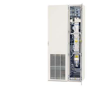
Дизайн
The Basic Line Modules are available in different frame sizes.
With frame sizes FB and GB, a fully controlled thyristor bridge is used to pre-charge the Basic Line Modules and connected Motor Modules. The thyristors normally operate with a trigger delay angle of 0°.
Basic Line Modules, frame size GD for 900 kW (400 V) or 1500 kW (690 V) include a diode bridge, and the DC link is precharged via a separate line-side pre-charging device that is located in the Line Connection Module (option L43, Line Connection Module for Basic Line Module).
Parallel connection of Basic Line Modules to increase the power rating
Line Modules can be connected in parallel (relative to the line supply) in two ways for the purpose of creating drive line-ups with a higher power rating.
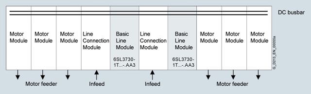
Two Basic Line Modules supplied with power via two separate Line Connection Modules
With this arrangement, a Basic Line Module is supplied by a Line Connection Module and the Basic Line Modules are protected by fuses or circuit breakers (at I > 800 A) in the Line Connection Module. A Basic Line Module is assigned to a Line Connection Module and is mechanically coupled. It is not necessary to mechanically directly couple both "groups" comprising Line Connection Module and Basic Line Module. Other modules can also be inserted in between.
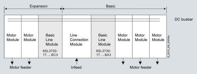
Two Basic Line Modules supplied with power via a single Line Connection Module
Basic Line Modules are available that can be operated on a single Line Connection Module. These can be connected to the left and right of the Line Connection Module. The power connections on the Basic Line Module on the left of the Line Connection Module are a mirror image (Order No. with "C"in the next to last position, example: 6SL3730-1T.41-.BC3), which results in a very compact design for the line infeed.
For additional information, please refer to the SINAMICS Low Voltage Engineering Manual.
These module versions feature integrated line-side fuses which are required because the circuit breaker in the Line Connection Module is not capable of providing selective protection for the Basic Line Modules. They are therefore 200 mm wider in each case than version 6SL3730-1T...-.AA3.
Note:
If the Basic Line Modules are supplied with power via the same circuit breaker, line-side fuses are provided to ensure selective individual protection of the modules. This arrangement increases the cabinet width by 200 mm (dimension data in selection tables includes extra width).
Please note that only Basic Line Modules with exactly the same output rating may be connected in parallel. The potential for imbalances in current distribution means that a current derating of 7.5 % applies; this must be taken into account when the modules are dimensioned.
A connection of the Basic Line Modules connected in parallel using DRIVE-CLiQ must be taken into consideration.
For additional information, please refer to the SINAMICS Low Voltage Engineering Manual.
Интеграция
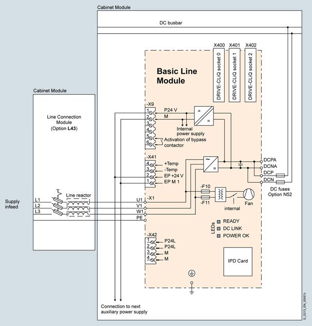
Connection example of a Basic Line Module
Опции
The table below lists the options available for Basic Line Modules (Details → Description of the options):
Available options | Order code |
|---|---|
CBC10 Communication Board | G20 1) |
CBE20 Communication Board | G33 1) |
AOP30 Advanced Operator Panel installed in the cabinet door | K08 1) |
CU320-2 DP Control Unit | K90 |
Performance expansion for CU320-2 | K94 1) |
Control Unit CU320‑2 PN | K95 |
Cabinet anti-condensation heating | L55 |
25/125 kW braking unit (can be used for frame size FB) for line voltages of 380 … 480 V and 660V … 690 V | L61 |
50/250 kW braking unit (can be used for frame size GB/GD) for line voltages of 380 … 480 V and 660 … 690 V | L62 |
25/125 kW braking unit (can be used for frame size FB) for line voltages of 500 … 600 V | L64 |
50/250 kW braking unit (can be used for frame size GB/GD) for line voltages of 500 … 600 V | L65 |
Base 100 mm high, RAL 7022 | M06 |
Cable-marshalling space 200 mm high, RAL 7035 | M07 |
IP21 degree of protection | M21 |
IP23 degree of protection (includes M60) | M23 |
Side panel mounted at the right | M26 |
Side panel mounted at the left | M27 |
IP43 degree of protection (includes M60) | M43 |
IP54 degree of protection (includes M60) | M54 |
Closed cabinet door, air intake from below through floor opening | M59 |
Additional touch protection (included in M23, M43 and M54) | M60 |
DC busbar system (Id = 1170 A, 1 × 60 × 10 mm) | M80 |
DC busbar system (Id = 1500 A, 1 × 80 × 10 mm) | M81 |
DC busbar system (Id = 1840 A, 1 × 100 × 10 mm) | M82 |
DC busbar system (Id = 2150 A, 2 × 60 × 10 mm) | M83 |
DC busbar system (Id = 2730 A, 2 × 80 × 10 mm) | M84 |
DC busbar system (Id = 3320 A, 2 × 100 × 10 mm) | M85 |
DC busbar system (Id = 3720 A, 3 × 80 × 10 mm) | M86 |
DC busbar system (Id = 4480 A, 3 × 100 × 10 mm) | M87 |
Crane transport assembly (top-mounted) | M90 |
DC link fuses for BLM | N52 |
Special paint finish for cabinet | Y09 |
Factory assembly as transport units | Y11 |
One-line label for system identification, 40 × 80 mm | Y31 |
Two-line label for system identification, 40 × 180 mm | Y32 |
Four-line label for system identification, 40 × 180 mm | Y33 |
Customer documentation (circuit diagram, erminal diagram, layout diagram) in DXF format | D02 |
Preliminary version of customer documentation in PDF format | D14 |
Documentation in English/French | D58 |
Documentation in English/Spanish | D60 |
Documentation in English/Italian | D80 |
Without Operating Instructions | D99 |
Rating plate data in English/French | T58 |
Rating plate data in English/Spanish | T60 |
Rating plate data in English/Italian | T80 |
Visual acceptance | F03 |
Function test without connected motor | F71 |
Insulation test | F77 |
Customer-specific acceptance inspections (on request) | F97 |
1) Only together with option K90 or K95.
Option selection matrix for Basic Line Modules
Certain options can mutually exclude one another (options that are not involved are not shown).
✓ | Possible combination |
|---|---|
– | Combination not possible |
Electrical options
| G20 | G33 | K90 | K95 | L61/64 | L62/65 |
|---|---|---|---|---|---|---|
G20 |
| – | ✓ | ✓ | ✓ | ✓ |
G33 | – |
| ✓ | ✓ | ✓ | ✓ |
K90 | ✓ | ✓ |
| – | ✓ | ✓ |
K95 | ✓ | ✓ | – |
| ✓ | ✓ |
L61/64 | ✓ | ✓ | ✓ | ✓ |
| – |
L62/65 | ✓ | ✓ | ✓ | ✓ | – |
|
Mechanical/electrical options
| M06 | M07 | M21 | M23 | M26 | M27 | M43 | M54 | M60 | M90 | Y11 | Y31 | Y32 | Y33 |
|---|---|---|---|---|---|---|---|---|---|---|---|---|---|---|
M06 |
| – | ✓ | ✓ | ✓ | ✓ | ✓ | ✓ | ✓ | ✓ | ✓ | ✓ | ✓ | ✓ |
M07 | – |
| ✓ | ✓ | ✓ | ✓ | ✓ | ✓ | ✓ | ✓ | ✓ | ✓ | ✓ | ✓ |
M21 | ✓ | ✓ |
| – | ✓ | ✓ | – | – | ✓ | ✓ | ✓ | ✓ | ✓ | ✓ |
M23 | ✓ | ✓ | – |
| ✓ | ✓ | – | – | – 1) | ✓ | ✓ | ✓ | ✓ | ✓ |
M26 | ✓ | ✓ | ✓ | ✓ |
| – | ✓ | ✓ | ✓ | ✓ | ✓ | ✓ | ✓ | ✓ |
M27 | ✓ | ✓ | ✓ | ✓ | – |
| ✓ | ✓ | ✓ | ✓ | ✓ | ✓ | ✓ | ✓ |
M43 | ✓ | ✓ | – | – | ✓ | ✓ |
| – | – 1) | ✓ | ✓ | ✓ | ✓ | ✓ |
M54 | ✓ | ✓ | – | – | ✓ | ✓ | – |
| – 1) | ✓ | ✓ | ✓ | ✓ | ✓ |
M60 | ✓ | ✓ | ✓ | – 1) | ✓ | ✓ | – 1) | – 1) |
| ✓ | ✓ | ✓ | ✓ | ✓ |
M90 | ✓ | ✓ | ✓ | ✓ | ✓ | ✓ | ✓ | ✓ | ✓ |
| – | ✓ | ✓ | ✓ |
Y11 | ✓ | ✓ | ✓ | ✓ | ✓ | ✓ | ✓ | ✓ | ✓ | – |
| ✓ | ✓ | ✓ |
Y31 | ✓ | ✓ | ✓ | ✓ | ✓ | ✓ | ✓ | ✓ | ✓ | ✓ | ✓ |
| – | – |
Y32 | ✓ | ✓ | ✓ | ✓ | ✓ | ✓ | ✓ | ✓ | ✓ | ✓ | ✓ | – |
| – |
Y33 | ✓ | ✓ | ✓ | ✓ | ✓ | ✓ | ✓ | ✓ | ✓ | ✓ | ✓ | – | – |
|
1) The option M60 is included in M23, M43 and M54.
DC busbar system mechanical options (busbars between individual Cabinet Modules)
| M80 | M81 | M82 | M83 | M84 | M85 | M86 | M87 |
|---|---|---|---|---|---|---|---|---|
M80 |
| – | – | ✓ | – | – | – | – |
M81 | – |
| – | – | ✓ | – | ✓ | – |
M82 | – | – |
| – | – | ✓ | – | ✓ |
M83 | ✓ | – | – |
| – | – | – | – |
M84 | – | ✓ | – | – |
| – | ✓ | – |
M85 | – | – | ✓ | – | – |
| – | ✓ |
M86 | – | ✓ | – | – | ✓ | – |
| – |
M87 | – | – | ✓ | – | – | ✓ | – |
|
Documentation
| D02 | D14 | D58 | D60 | D80 | D99 |
|---|---|---|---|---|---|---|
D02 |
| ✓ | ✓ | ✓ | ✓ | – |
D14 | ✓ |
| ✓ | ✓ | ✓ | – |
D58 | ✓ | ✓ |
| – | – | – |
D60 | ✓ | ✓ | – |
| – | – |
D80 | ✓ | ✓ | – | – |
| – |
D99 | – | – | – | – | – |
|
Rating plate data
| T58 | T60 | T80 |
|---|---|---|---|
T58 |
| – | – |
T60 | – |
| – |
T80 | – | – |
|
Технические данные
Line voltage 380 … 480 V 3 AC | Basic Line Modules | ||||||
|---|---|---|---|---|---|---|---|
| 6SL3730-1TE34-2AA3 | 6SL3730-1TE35-3AA3 | 6SL3730-1TE38-2AA3 | 6SL3730-1TE41-2AA3 | 6SL3730-1TE41-5AA3 | 6SL3730-1TE41-8AA3 | |
For a parallel circuit configuration, mounted to the right at the Line Connection Module |
|
|
| 6SL3730-1TE41-2BA3 | 6SL3730-1TE41-5BA3 | 6SL3730-1TE41-8BA3 | |
For a parallel circuit configuration, mounted to the left at the Line Connection Module |
|
|
| 6SL3730-1TE41-2BC3 | 6SL3730-1TE41-5BC3 | 6SL3730-1TE41-8BC3 | |
Rated power | |||||||
| kW | 200 | 250 | 400 | 560 | 710 | 900 |
| kW | 160 | 200 | 315 | 450 | 560 | 705 |
| hp | 305 | 385 | 615 | 860 | 1090 | 1390 |
| hp | 245 | 305 | 485 | 690 | 860 | 1090 |
DC link current | |||||||
| A | 420 | 530 | 820 | 1200 | 1500 | 1880 |
| A | 328 | 413 | 640 | 936 | 1170 | 1467 |
| A | 630 | 795 | 1230 | 1800 | 2250 | 2820 |
Input current | |||||||
| A | 365 | 460 | 710 | 1010 | 1265 | 1630 |
| A | 547 | 690 | 1065 | 1515 | 1897 | 2380 |
Current demand | |||||||
| A | 1.1 | 1.1 | 1.1 | 1.1 | 1.1 | 1.1 |
| A | Internal | Internal | Internal | Internal | Internal | Internal |
DC link capacitance | |||||||
| μF | 7200 | 9600 | 14600 | 23200 | 29000 | 34800 |
| μF | 57600 | 76800 | 116800 | 185600 | 232000 | 139200 |
Power loss, max. 3) | |||||||
| kW | 1.9 | 2.1 | 3.2 | 4.6 | 5.5 | 6.9 |
| kW | 1.9 | 2.1 | 3.2 | 4.6 | 5.5 | 6.9 |
Cooling air requirement | m3/s | 0.17 | 0.17 | 0.17 | 0.36 | 0.36 | 0.36 |
Sound pressure level LpA (1 m) at 50/60 Hz | dB | 66/68 | 66/68 | 66/68 | 71/73 | 71/73 | 71/73 |
PE/GND connection |
| PE bar | PE bar | PE bar | PE bar | PE bar | PE bar |
| mm2 | 600 | 600 | 600 | 600 | 600 | 600 |
| mm2 | 240 | 240 | 240 | 240 | 240 | 240 |
Cable length, max. 4) | |||||||
| m | 2600 | 2600 | 2600 | 4000 | 4000 | 4800 |
| m | 3900 | 3900 | 3900 | 6000 | 6000 | 7200 |
Degree of protection |
| IP20 | IP20 | IP20 | IP20 | IP20 | IP20 |
Dimensions | |||||||
| mm | 400 | 400 | 400 | 400/600/600 | 400/600/600 | 400/600/600 |
| mm | 2200 | 2200 | 2200 | |||


 Ответ от производителя может занять до 5 дней и более.

