Active Line Modules including Active Interface Modules Siemens
Обзор
Active Line Modules can supply energy and return regenerative energy to the supply system.
In contrast to Basic Line Modules and Smart Line Modules, Active Line Modules generate a controlled DC voltage that is kept constant despite fluctuations in the line voltage (the line voltage must remain within the permissible tolerance range). Active Line Modules draw a virtually sinusoidal current from the supply system and therefore do not cause any harmful current harmonics.
Braking Modules and braking resistors are required only if the drives need to be decelerated in a controlled manner after a power failure – i.e. when energy cannot be regenerated into the line supply.
Active Line Modules are available for the following voltages and power ratings:
Line voltage | Rated power |
|---|---|
80 … 480 V 3 AC | 132 … 900 kW |
500 … 690 V 3 AC | 560 … 1400 kW |
Дизайн
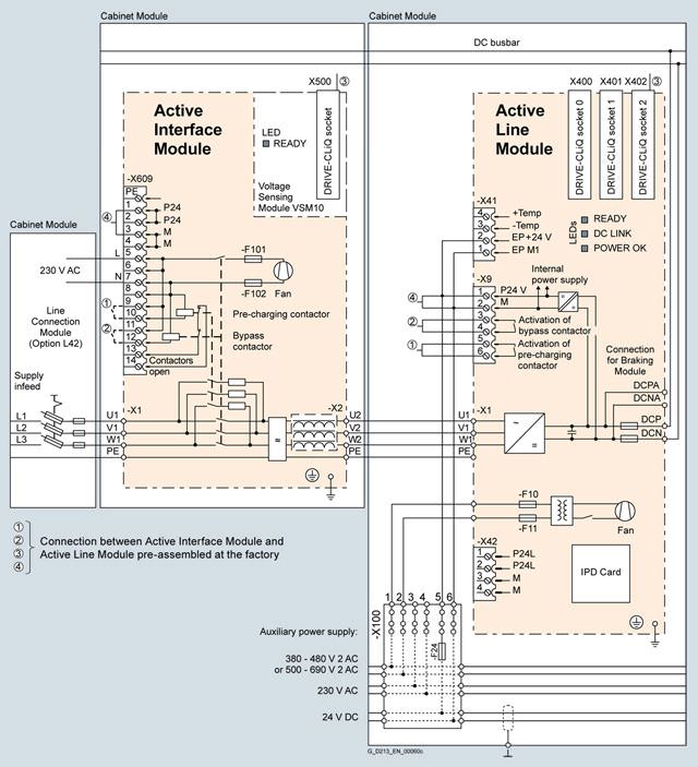
Active Line Modules are always operated together with an Active Interface Module, which contains the associated Clean Power Filter and pre-charging circuit. The integrated line filter ensures compliance with the EMC requirements for the "second environment".
The Active Line Module and Active Interface Module are supplied as a complete, fully wired unit, i.e., the customer does not need to supply any further cables or carry out any other wiring tasks.
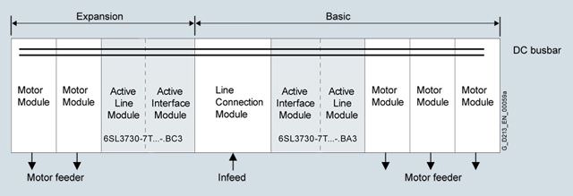
Parallel connection of Active Line Modules to increase power rating
Active Line Modules are available for creating drive line-ups with more power. These modules can be operated in parallel on a common Line Connection Module and are arranged to the right and left of the Line Connection Module.
The power connections on the Active Line Module on the left of the Line Connection Module are a mirror image (Order No. with "C" in the next to last position, example: 6SL3730-7T.41.-.BC3), which results in a very compact design for the line infeed.
Please note that only Active Line Modules with exactly the same power rating may be connected in parallel. The potential for imbalances in current distribution means that a current derating of 5 % applies; this must be taken into account when the modules are dimensioned.
A connection of the Active Line Modules connected in parallel using DRIVE-CLiQ must be taken into consideration.
For additional information, please refer to the SINAMICS Low Voltage Engineering Manual.
Интеграция
The Active Line Module is controlled by the CU320-2 Control Unit. Communication between the Control Unit and module is established via DRIVE-CLiQ connections. The Active Interface Module is included in the scope of delivery for the Active Line Module.
Example of connection of an Active Line Module (frame size FI/FX and GI/GX)
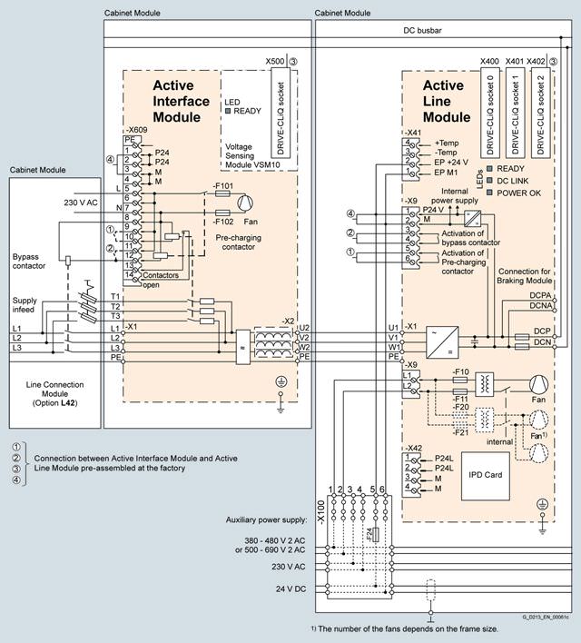
Example of connection of an Active Line Module (frame size HI/HX and JI/JX)
Опции
The table below lists the options available for Active Line Modules (Details → Description of the options):
Available options | Order code |
|---|---|
CBC10 Communication Board | G20 1) |
CBE20 Communication Board | G33 1) |
AOP30 Advanced Operator Panel installed in the cabinet door | K08 1) |
CU320-2 DP Control Unit | K90 |
Performance expansion for CU320-2 | K94 1) |
Control Unit CU320‑2 PN | K95 |
Cabinet anti-condensation heating | L55 |
25/125 kW braking unit (can be used for frame size FB) for line voltages of 380 … 480 V and 660V … 690 V | L61 |
50/250 kW braking unit (can be used for frame size GB/GD) for line voltages of 380 … 480 V and 660 … 690 V | L62 |
25/125 kW braking unit (can be used for frame size FB) for line voltages of 500 … 600 V | L64 |
50/250 kW braking unit (can be used for frame size GB/GD) for line voltages of 500 … 600 V | L65 |
Base 100 mm high, RAL 7022 | M06 |
Cable-marshalling space 200 mm high, RAL 7035 | M07 |
IP21 degree of protection | M21 |
IP23 degree of protection (includes M60) | M23 |
Side panel mounted at the right | M26 |
Side panel mounted at the left | M27 |
IP43 degree of protection (includes M60) | M43 |
IP54 degree of protection (includes M60) | M54 |
Closed cabinet door, air intake from below through floor opening | M59 |
Additional touch protection (included in M23, M43 and M54) | M60 |
DC busbar system (Id = 1170 A, 1 × 60 × 10 mm) | M80 |
DC busbar system (Id = 1500 A, 1 × 80 × 10 mm) | M81 |
DC busbar system (Id = 1840 A, 1 × 100 × 10 mm) | M82 |
DC busbar system (Id = 2150 A, 2 × 60 × 10 mm) | M83 |
DC busbar system (Id = 2730 A, 2 × 80 × 10 mm) | M84 |
DC busbar system (Id = 3320 A, 2 × 100 × 10 mm) | M85 |
DC busbar system (Id = 3720 A, 3 × 80 × 10 mm) | M86 |
DC busbar system (Id = 4480 A, 3 × 100 × 10 mm) | M87 |
Crane transport assembly (top-mounted) | M90 |
Special paint finish for cabinet | Y09 |
Factory assembly as transport units | Y11 |
One-line label for system identification, 40 × 80 mm | Y31 |
Two-line label for system identification, 40 × 180 mm | Y32 |
Four-line label for system identification, 40 × 180 mm | Y33 |
Customer documentation (circuit diagram, erminal diagram, layout diagram) in DXF format | D02 |
Preliminary version of customer documentation in PDF format | D14 |
Documentation in English/French | D58 |
Documentation in English/Spanish | D60 |
Documentation in English/Italian | D80 |
Without Operating Instructions | D99 |
Rating plate data in English/French | T58 |
Rating plate data in English/Spanish | T60 |
Rating plate data in English/Italian | T80 |
Visual acceptance | F03 |
Function test without connected motor | F71 |
Insulation test | F77 |
Customer-specific acceptance inspections (on request) | F97 |
1) Only together with option K90 or K95.
Option selection matrix for Active Line Modules
Certain options can mutually exclude one another
(options that are not involved are not shown).
✓ | Possible combination |
|---|---|
– | Combination not possible |
Electrical options
| G20 | G33 | K90 | K95 | L61/64 | L62/65 |
|---|---|---|---|---|---|---|
G20 |
| – | ✓ | ✓ | ✓ | ✓ |
G33 | – |
| ✓ | ✓ | ✓ | ✓ |
K90 | ✓ | ✓ |
| – | ✓ | ✓ |
K95 | ✓ | ✓ | – |
| ✓ | ✓ |
L61/64 | ✓ | ✓ | ✓ | ✓ |
| – |
L62/65 | ✓ | ✓ | ✓ | ✓ | – |
|
Mechanical/electrical options
| M06 | M07 | M21 | M23 | M26 | M27 | M43 | M54 | M60 | M90 | Y11 | Y31 | Y32 | Y33 |
|---|---|---|---|---|---|---|---|---|---|---|---|---|---|---|
M06 |
| – | ✓ | ✓ | ✓ | ✓ | ✓ | ✓ | ✓ | ✓ | ✓ | ✓ | ✓ | ✓ |
M07 | – |
| ✓ | ✓ | ✓ | ✓ | ✓ | ✓ | ✓ | ✓ | ✓ | ✓ | ✓ | ✓ |
M21 | ✓ | ✓ |
| – | ✓ | ✓ | – | – | ✓ | ✓ | ✓ | ✓ | ✓ | ✓ |
M23 | ✓ | ✓ | – |
| ✓ | ✓ | – | – | – 1) | ✓ | ✓ | ✓ | ✓ | ✓ |
M26 | ✓ | ✓ | ✓ | ✓ |
| – | ✓ | ✓ | ✓ | ✓ | ✓ | ✓ | ✓ | ✓ |
M27 | ✓ | ✓ | ✓ | ✓ | – |
| ✓ | ✓ | ✓ | ✓ | ✓ | ✓ | ✓ | ✓ |
M43 | ✓ | ✓ | – | – | ✓ | ✓ |
| – | – 1) | ✓ | ✓ | ✓ | ✓ | ✓ |
M54 | ✓ | ✓ | – | – | ✓ | ✓ | – |
| – 1) | ✓ | ✓ | ✓ | ✓ | ✓ |
M60 | ✓ | ✓ | ✓ | – 1) | ✓ | ✓ | – 1) | – 1) |
| ✓ | ✓ | ✓ | ✓ | ✓ |
M90 | ✓ | ✓ | ✓ | ✓ | ✓ | ✓ | ✓ | ✓ | ✓ |
| – | ✓ | ✓ | ✓ |
Y11 | ✓ | ✓ | ✓ | ✓ | ✓ | ✓ | ✓ | ✓ | ✓ | – |
| ✓ | ✓ | ✓ |
Y31 | ✓ | ✓ | ✓ | ✓ | ✓ | ✓ | ✓ | ✓ | ✓ | ✓ | ✓ |
| – | – |
Y32 | ✓ | ✓ | ✓ | ✓ | ✓ | ✓ | ✓ | ✓ | ✓ | ✓ | ✓ | – |
| – |
Y33 | ✓ | ✓ | ✓ | ✓ | ✓ | ✓ | ✓ | ✓ | ✓ | ✓ | ✓ | – | – |
|
1) The option M60 is included in M23, M43 and M54.
DC busbar system mechanical options (busbars between individual Cabinet Modules)
| M80 | M81 | M82 | M83 | M84 | M85 | M86 | M87 |
|---|---|---|---|---|---|---|---|---|
M80 |
| – | – | ✓ | – | – | – | – |
M81 | – |
| – | – | ✓ | – | ✓ | – |
M82 | – | – |
| – | – | ✓ | – | ✓ |
M83 | ✓ | – | – |
| – | – | – | – |
M84 | – | ✓ | – | – |
| – | ✓ | – |
M85 | – | – | ✓ | – | – |
| – | ✓ |
M86 | – | ✓ | – | – | ✓ | – |
| – |
M87 | – | – | ✓ | – | – | ✓ | – |
|
Documentation
| D02 | D14 | D58 | D60 | D80 | D99 |
|---|---|---|---|---|---|---|
D02 |
| ✓ | ✓ | ✓ | ✓ | – |
D14 | ✓ |
| ✓ | ✓ | ✓ | – |
D58 | ✓ | ✓ |
| – | – | – |
D60 | ✓ | ✓ | – |
| – | – |
D80 | ✓ | ✓ | – | – |
| – |
D99 | – | – | – | – | – |
|
Rating plate data
| T58 | T60 | T80 |
|---|---|---|---|
T58 |
| – | – |
T60 | – |
| – |
T80 | – | – |
|
Технические данные
Line voltage 380 … 480 V 3 AC | Active Line Modules | ||||||||
|---|---|---|---|---|---|---|---|---|---|
| 6SL3730-7TE32-1BA3 | 6SL3730-7TE32-6BA3 | 6SL3730-7TE33-8BA3 | 6SL3730-7TE35-0BA3 | 6SL3730-7TE36-1BA3 | 6SL3730-7TE38-4BA3 | 6SL3730-7TE41-0BA3 | 6SL3730-7TE41-4BA3 | |
For a parallel circuit configuration, mounted to the left at the Line Connection Module |
|
|
|
|
|
| 6SL3730-7TE41-0BC3 | 6SL3730-7TE41-4BC3 | |
Rated power | |||||||||
| kW | 132 | 160 | 235 | 300 | 380 | 500 | 630 | 900 |
| kW | 115 | 145 | 210 | 270 | 335 | 465 | 545 | 780 |
| hp | 200 | 250 | 400 | 500 | 600 | 700 | 900 | 1250 |
| hp | 150 | 200 | 300 | 400 | 500 | 700 | 800 | 1000 |
DC link current | |||||||||
| A | 235 | 291 | 425 | 549 | 678 | 940 | 1103 | 1574 |
| A | 209 | 259 | 378 | 489 | 603 | 837 | 982 | 1404 |
| A | 352 | 436 | 637 | 823 | 1017 | 1410 | 1654 | 2361 |
Infeed/regenerative feedback current | |||||||||
| A | 210 | 260 | 380 | 490 | 605 | 840 | 985 | 1405 |
| A | 315 | 390 | 570 | 735 | 907 | 1260 | 1477 | 2107 |
Current demand | |||||||||
| A | 1.27 | 1.27 | 1.52 | 1.52 | 1.57 | 1.57 | 1.67 | 1.67 |
| A | 0.6 | 0.6 | 1.2 | 1.2 | 4.6 | 4.6 | 4.9 | 4.9 |
| A | 0.63 | 1.13 | 1.8 | 1.8 | 3.6 | 3.6 | 5.4 | 5.4 |
DC link capacitance | |||||||||
| μF | 4200 | 5200 | 7800 | 9600 | 12600 | 16800 | 18900 | 28800 |
| μF | 41600 | 41600 | 76800 | 76800 | 134400 | 134400 | 230400 | 230400 |
Power loss, max. 3) | |||||||||
| kW | 4.3 | 4.9 | 6.9 | 8.7 | 11.7 | 13.8 | 17.6 | 21.8 |
| kW | 4.4 | 5.1 | 7.2 | 9.0 | 12.1 | 14.3 | 18.3 | 22.7 |
Cooling air requirement | m3/s | 0.65 | 0.65 | 1.3 | 1.3 | 1.58 | 1.58 | 1.88 | 1.88 |
Sound pressure level LpA 4) (1 m) at 50/60 Hz | dB | 71/73 | 71/73 | 72/74 | 72/74 | 77/79 | 77/79 | 78/80 | 78/80 |
PE/GND connection |
| PE bar | PE bar | PE bar | PE bar | PE bar | PE bar | PE bar | PE bar |
| mm2 | 600 | 600 | 600 | 600 | 600 | 600 | 600 | 600 |
| mm2 | 240 | 240 | 240 | 240 | 240 | 240 | 240 | 240 |
Cable length, max. 5) | |||||||||
| m | 2700 | 2700 | 2700 | 2700 | 3900 | 3900 | 3900 | 3900 |
| m | 4050 | 4050 | 4050 | 4050 | 5850 | 5850 | 5850 | 5850 |
Degree of protection |
| IP20 | IP20 | IP20 | IP20 | IP20 | Запрос коммерческого предложения× Сообщение отправлено× В ближайшее время сообщение будет обработано. Письмо с номером обращения отправлено на Ваш почтовый ящик. Спасибо за то, что выбрали Первый ZIP! Что-то пошло не так...× К сожалению, наша система расценила Ваше сообщение как спам. Если это произошло по ошибке, пожалуйста, обратитесь к нам по электронной почте. Приносим извинения за возможные неудобства.  Вы отправляете нам запрос  Если у нас есть прайс-лист, мы отправляем Вам ответ в течение дня. А если у нас нет прайс-листа по запрошенным товарам?     Если у нас нет прайс-листа, мы отправляем запрос производителю.  Ответ от производителя может занять до 5 дней и более. Ответ от производителя может занять до 5 дней и более.  Запрос производителю мы отправляем только для конечных потребителей.  Торгующим организациям коммерческие предложения предоставляются только по прайсовым позициям: Siemens Beckhoff Pepperl+Fuchs Phoenix Contact PILZ Turck Leuze Electronic Endress+Hauser Murr Elektronik Schmersal | ||