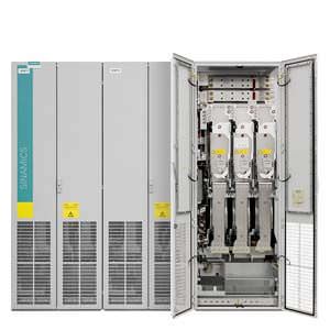
Motor Modules chassis format Siemens
Обзор
Motor Modules in the chassis format are available in the power range from 75 kW to 1200 kW.
Line voltage | DC link voltage | Type rating |
|---|---|---|
380 … 480 V 3 AC | 510 … 720 V DC | 110 … 800 kW |
500 … 690 V 3 AC | 675 … 1035 V DC | 75 … 1200 kW |
By connecting in parallel up to 4 Motor Modules, which are operated on one Control Unit and supply one motor, it is possible to increase the available shaft power to max. approx. 4500 kW (taking into account the derating factors according to the SINAMICS Low Voltage Engineering Manual).
SINAMICS S120 Motor Modules in the chassis format and Cabinet Modules can also be used as a braking module, if, instead of a motor, a 3-phase braking resistor is connected.
For more detailed information on this topic, please refer to the SINAMICS Low Voltage Engineering Manual.
Дизайн
Motor Modules in the chassis format contain the following components:
- Retaining device for the DC busbar, including the connection to the DC connections of the Motor Module
- Nickel-plated connection busbars for motor cables for Motor Modules, frame sizes FX and GX; for Motor Modules, frame sizes HX and JX, the connection is made directly on the unit
- Cable propping bar for the electric power cables
- DRIVE-CLiQ interface (3 DRIVE-CLiQ sockets), without Control Unit
- Customer interface -X55
- Auxiliary power supply system (6-pole) for the auxiliary power supply, including cable connections for looping through to the next Cabinet Module
- Nickel-plated PE busbar (60 × 10 mm), including jumper for looping through to the next Cabinet Module
- EMC-compliant design thanks to additional shielding measures and appropriate laying of cables.
Интеграция
Motor Modules are controlled by the CU320-2 DP or CU320-2 PN Control Unit. Communication between the Control Unit and Modules is established via a DRIVE-CLiQ connection.
If the Control Unit is integrated as an option with order code K90 or K95 in the same cabinet, then these communication cables will already be installed. If the Control Unit is to be mounted externally, the DRIVE-CLiQ cable will not be included in the scope of delivery and must be configured on site.
For additional information, please refer to the SINAMICS Low Voltage Engineering Manual.
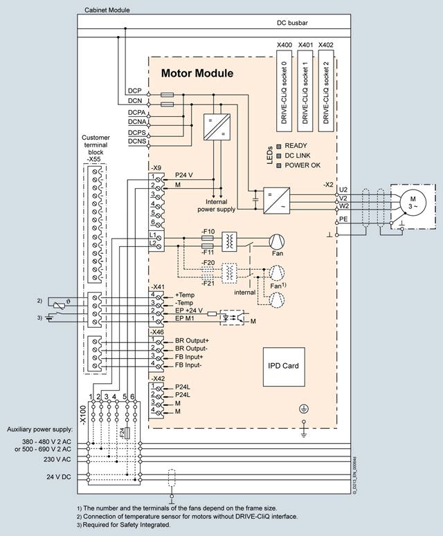
Connection example: Motor Module, chassis format
Опции
The table below lists the options available for Motor Modules (Details → Description of the options):
Available options | Order code |
|---|---|
CBC10 Communication Board | G20 1) |
CBE20 Communication Board | G33 1) |
Safety license for 1 to 5 axes | K01 to K05 |
AOP30 Advanced Operator Panel installed in the cabinet door | K08 1) |
SMC10 Sensor Module Cabinet-Mounted | K46 |
SMC20 Sensor Module Cabinet-Mounted | K48 |
SMC30 Sensor Module Cabinet-Mounted | K50 |
VSM10 Voltage Sensing Module | K51 |
Terminal module for controlling the Safe Torque Off and Safe Stop 1 safety functions | K82 |
TM54F Terminal Module | K87 |
Safe Brake Adapter SBA, 230 V AC | K88 |
Safe Brake Adapter SBA, 24 V DC | K89 |
CU320‑2 DP Control Unit | K90 |
Performance expansion for CU320-2 Control Unit | K94 1) |
CU320‑2 PN Control Unit | K95 |
dv/dt filter compact plus Voltage Peak Limiter | L07 |
Motor reactor | L08 |
dv/dt filter plus Voltage Peak Limiter | L10 |
Output-side circuit breaker (motor-driven) | L34 |
DC interface incl. pre-charging circuit of the associated DC link capacitance (includes M60) | L37 |
Cabinet anti-condensation heating | L55 |
25/125 kW braking unit (can be used for frame size FX) for line voltages of 380 ... 480 V and 660 ... 690 V | L61 |
50/250 kW braking unit (can be used for frame size GX/HX/JX) for line voltages of 380 ... 480 V and 660 ... 690 V | L62 |
25/125 kW braking unit (can be used for frame size FX) for line voltages of 500 … 600 V | L64 |
50/250 kW braking unit (can be used for frame size GX/HX/JX) for line voltages of 500 … 600 V | L65 |
Base 100 mm high, RAL 7022 | M06 |
Cable-marshalling space 200 mm high, RAL 7035 | M07 |
IP21 degree of protection | M21 |
IP23 degree of protection (includes M60) | M23 |
Side panel mounted at the right | M26 |
Side panel mounted at the left | M27 |
IP43 degree of protection (includes M60) | M43 |
IP54 degree of protection (includes M60) | M54 |
Closed cabinet door, air intake from below through floor opening | M59 |
Additional touch protection (included in M23, M43 and M54) | M60 |
EMC shield bus | M70 |
DC busbar system (Id = 1170 A, 1 × 60 × 10 mm) | M80 |
DC busbar system (Id = 1500 A, 1 × 80 × 10 mm) | M81 |
DC busbar system (Id = 1840 A, 1 × 100 × 10 mm) | M82 |
DC busbar system (Id = 2150 A, 2 × 60 × 10 mm) | M83 |
DC busbar system (Id = 2730 A, 2 × 80 × 10 mm) | M84 |
DC busbar system (Id = 3320 A, 2 × 100 × 10 mm) | M85 |
DC busbar system (Id = 3720 A, 3 × 80 × 10 mm) | M86 |
DC busbar system (Id = 4480 A, 3 × 100 × 10 mm) | M87 |
Crane transport assembly (top-mounted) | M90 |
Special paint finish for cabinet | Y09 |
Factory assembly as transport units | Y11 |
One-line label for system identification, 40 × 80 mm | Y31 |
Two-line label for system identification, 40 × 180 mm | Y32 |
Four-line label for system identification, 40 × 180 mm | Y33 |
Customer documentation (circuit diagram, terminal diagram, layout diagram) in DXF format | D02 |
Preliminary version of customer documentation in PDF format | D14 |
Documentation in English/French | D58 |
Documentation in English/Spanish | D60 |
Documentation in English/Italian | D80 |
Without Operating Instructions | D99 |
Rating plate data in English/French | T58 |
Rating plate data in English/Spanish | T60 |
Rating plate data in English/Italian | T80 |
Visual acceptance | F03 |
Function test without connected motor | F71 |
Insulation test | F77 |
Customer-specific acceptance inspections (on request) | F97 |
1) Only together with option K90 or K95.
Option selection matrix for Motor Modules in the chassis format
Certain options can mutually exclude one another
(options that are not involved are not shown).
✓ | Possible combination |
|---|---|
– | Combination not possible |
Electrical options
| G20 | G33 | K46 | K48 | K50 | K51 | K88 | K89 | K90 | K95 | L07 | L08 | L10 | L34 | L37 | L61/64 | L62/65 |
|---|---|---|---|---|---|---|---|---|---|---|---|---|---|---|---|---|---|
G20 |
| – | ✓ | ✓ | ✓ | ✓ | ✓ | ✓ | ✓ | ✓ | ✓ | ✓ | ✓ | ✓ | ✓ | ✓ | ✓ |
G33 | – |
| ✓ | ✓ | ✓ | ✓ | ✓ | ✓ | ✓ | ✓ | ✓ | ✓ | ✓ | ✓ | ✓ | ✓ | ✓ |
K46 | ✓ | ✓ |
| – | – | – | ✓ | ✓ | ✓ | ✓ | ✓ | ✓ | ✓ | ✓ | ✓ | ✓ | ✓ |
K48 | ✓ | ✓ | – |
| – | – | ✓ | ✓ | ✓ | ✓ | ✓ | ✓ | ✓ | ✓ | ✓ | ✓ | ✓ |
K50 | ✓ | ✓ | – | – |
| – | ✓ | ✓ | ✓ | ✓ | ✓ | ✓ | ✓ | ✓ | ✓ | ✓ | ✓ |
K51 | ✓ | ✓ | – | – | – |
| ✓ | ✓ | ✓ | ✓ | ✓ | ✓ | ✓ | ✓ | ✓ | ✓ | ✓ |
K88 | ✓ | ✓ | ✓ | ✓ | ✓ | ✓ |
| – | ✓ | ✓ | ✓ | ✓ | ✓ | ✓ | ✓ | ✓ | ✓ |
K89 | ✓ | ✓ | ✓ | ✓ | ✓ | ✓ | – |
| ✓ | ✓ | ✓ | ✓ | ✓ | ✓ | ✓ | ✓ | ✓ |
K90 | ✓ | ✓ | ✓ | ✓ | ✓ | ✓ | ✓ | ✓ |
| – | ✓ | ✓ | ✓ | ✓ | ✓ | ✓ | ✓ |
K95 | ✓ | ✓ | ✓ | ✓ | ✓ | ✓ | ✓ | ✓ | – |
| ✓ | ✓ | ✓ | ✓ | ✓ | ✓ | ✓ |
L07 | ✓ | ✓ | ✓ | ✓ | ✓ | ✓ | ✓ | ✓ | ✓ | ✓ |
| – | – | ✓ | – | ✓ | ✓ |
L08 | ✓ | ✓ | ✓ | ✓ | ✓ | ✓ | ✓ | ✓ | ✓ | ✓ | – |
| – | ✓ | ✓ | ✓ | ✓ |
L10 | ✓ | ✓ | ✓ | ✓ | ✓ | ✓ | ✓ | ✓ | ✓ | ✓ | – | – |
| – | ✓ | ✓ | ✓ |
L34 | ✓ | ✓ | ✓ | ✓ | ✓ | ✓ | ✓ | ✓ | ✓ | ✓ | ✓ | ✓ | – |
| ✓ | ✓ | ✓ |
L37 | ✓ | ✓ | ✓ | ✓ | ✓ | ✓ | ✓ | ✓ | ✓ | ✓ | – | ✓ | ✓ | ✓ |
| – | – |
L61/64 | ✓ | ✓ | ✓ | ✓ | ✓ | ✓ | ✓ | ✓ | ✓ | ✓ | ✓ | ✓ | ✓ | ✓ | – |
| – |
L62/65 | ✓ | ✓ | ✓ | ✓ | ✓ | ✓ | ✓ | ✓ | ✓ | ✓ | ✓ | ✓ | ✓ | ✓ | – | – |
|
Mechanical/electrical options
| M06 | M07 | M21 | M23 | M26 | M27 | M43 | M54 | M60 | M90 | Y11 | Y31 | Y32 | Y33 |
|---|---|---|---|---|---|---|---|---|---|---|---|---|---|---|
M06 |
| – | ✓ | ✓ | ✓ | ✓ | ✓ | ✓ | ✓ | ✓ | ✓ | ✓ | ✓ | ✓ |
M07 | – |
| ✓ | ✓ | ✓ | ✓ | ✓ | ✓ | ✓ | ✓ | ✓ | ✓ | ✓ | ✓ |
M21 | ✓ | ✓ |
| – | ✓ | ✓ | – | – | ✓ | ✓ | ✓ | ✓ | ✓ | ✓ |
M23 | ✓ | ✓ | – |
| ✓ | ✓ | – | – | – 1) | ✓ | ✓ | ✓ | ✓ | ✓ |
M26 | ✓ | ✓ | ✓ | ✓ |
| – | ✓ | ✓ | ✓ | ✓ | ✓ | ✓ | ✓ | ✓ |
M27 | ✓ | ✓ | ✓ | ✓ | – |
| ✓ | ✓ | ✓ | ✓ | ✓ | ✓ | ✓ | ✓ |
M43 | ✓ | ✓ | – | – | ✓ | ✓ |
| – | – 1) | ✓ | ✓ | ✓ | ✓ | ✓ |
M54 | ✓ | ✓ | – | – | ✓ | ✓ | – |
| – 1) | ✓ | ✓ | ✓ | ✓ | ✓ |
M60 | ✓ | ✓ | ✓ | – 1) | ✓ | ✓ | – 1) | – 1) |
| ✓ | ✓ | ✓ | ✓ | ✓ |
M90 | ✓ | ✓ | ✓ | ✓ | ✓ | ✓ | ✓ | ✓ | ✓ |
| – | ✓ | ✓ | ✓ |
Y11 | ✓ | ✓ | ✓ | ✓ | ✓ | ✓ | ✓ | ✓ | ✓ | – |
| ✓ | ✓ | ✓ |
Y31 | ✓ | ✓ | ✓ | ✓ | ✓ | ✓ | ✓ | ✓ | ✓ | ✓ | ✓ |
| – | – |
Y32 | ✓ | ✓ | ✓ | ✓ | ✓ | ✓ | ✓ | ✓ | ✓ | ✓ | ✓ | – |
| – |
Y33 | ✓ | ✓ | ✓ | ✓ | ✓ | ✓ | ✓ | ✓ | ✓ | ✓ | ✓ | – | – |
|
1) The option M60 is included in L37, M23, M43 and M54.
DC busbar system mechanical options (busbars between individual Cabinet Modules)
| M80 | M81 | M82 | M83 | M84 | M85 | M86 | M87 |
|---|---|---|---|---|---|---|---|---|
M80 |
| – | – | ✓ | – | – | – | – |
M81 | – |
| – | – | ✓ | – | ✓ | – |
M82 | – | – |
| – | – | ✓ | – | ✓ |
M83 | ✓ | – | – |
| – | – | – | – |
M84 | – | ✓ | – | – |
| – | ✓ | – |
M85 | – | – | ✓ | – | – |
| – | ✓ |
M86 | – | ✓ | – | – | ✓ | – |
| – |
M87 | – | – | ✓ | – | – | ✓ | – |
|
Documentation
| D02 | D14 | D58 | D60 | D80 | D99 |
|---|---|---|---|---|---|---|
D02 |
| ✓ | ✓ | ✓ | ✓ | – |
D14 | ✓ |
| ✓ | ✓ | ✓ | – |
D58 | ✓ | ✓ |
| – | – | – |
D60 | ✓ | ✓ | – |
| – | – |
D80 | ✓ | ✓ | – | – |
| – |
D99 | – | – | – | – | – |
|
Rating plate data
| T58 | T60 | T80 |
|---|---|---|---|
T58 | Запрос коммерческого предложения× Сообщение отправлено× В ближайшее время сообщение будет обработано. Письмо с номером обращения отправлено на Ваш почтовый ящик. Спасибо за то, что выбрали Первый ZIP! Что-то пошло не так...× К сожалению, наша система расценила Ваше сообщение как спам. Если это произошло по ошибке, пожалуйста, обратитесь к нам по электронной почте. Приносим извинения за возможные неудобства.  Вы отправляете нам запрос  Если у нас есть прайс-лист, мы отправляем Вам ответ в течение дня. А если у нас нет прайс-листа по запрошенным товарам?     Если у нас нет прайс-листа, мы отправляем запрос производителю.  Ответ от производителя может занять до 5 дней и более. Ответ от производителя может занять до 5 дней и более.  Запрос производителю мы отправляем только для конечных потребителей.  Торгующим организациям коммерческие предложения предоставляются только по прайсовым позициям: Siemens Beckhoff Pepperl+Fuchs Phoenix Contact PILZ Turck Leuze Electronic Endress+Hauser Murr Elektronik Schmersal |