Auxiliary Power Supply Modules Siemens

Обзор
Auxiliary Power Supply Modules supply the auxiliary power supply for the SINAMICS S120 Cabinet Modules. Units connected to this auxiliary power supply system include the fans of the SINAMICS S120 devices installed in the Cabinet Modules. In addition, the auxiliary power supply system supplies the electronic modules with an external 24 V DC voltage. This is required when the DC link is not charged, for instance, in order to maintain PROFIBUS/PROFINET communication.
Дизайн
The Auxiliary Power Supply Module is connected in the customer''s plant to a voltage corresponding to the respective rated unit voltage.
The standard version contains the following components:
- Fuse switch disconnector with fuse monitoring for external evaluation
- Supply of the auxiliary power supply system with 3 fused auxiliary voltages:
- 24 V DC for the electronics power supply
- 230 V 2 AC to supply 230 V loads
- 380 V to 690 V 2 AC to supply the equipment fans
- Transformer with 230 V output voltage
- SITOP 24 V DC power supply
- 6-pole auxiliary power supply system (ready-wired), including connections for looping through to the next Cabinet Module
- Nickel-plated PE busbar (60 mm × 10 mm), including jumper for looping through to the next Cabinet Module
Интеграция
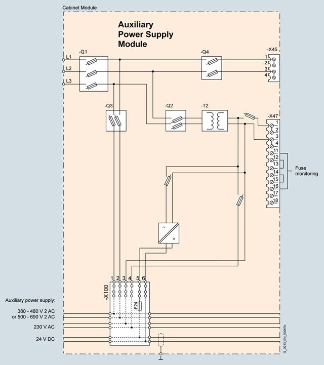
Block diagram, Auxiliary Power Supply Module
Опции
The table below lists the options available for Auxiliary Power Supply Modules (Details → Description of the options):
Available options | Order code |
|---|---|
Cabinet anti-condensation heating | L55 |
Base 100 mm high, RAL 7022 | M06 |
Cable-marshalling space 200 mm high, RAL 7035 | M07 |
IP21 degree of protection | M21 |
IP23 degree of protection | M23 |
Side panel mounted at the right | M26 |
Side panel mounted at the left | M27 |
IP43 degree of protection | M43 |
IP54 degree of protection | M54 |
Closed cabinet door, air intake from below through floor opening | M59 |
EMC shield bus | M70 |
DC busbar system (Id = 1170 A, 1 × 60 × 10 mm) | M80 |
DC busbar system (Id = 1500 A, 1 × 80 × 10 mm) | M81 |
DC busbar system (Id = 1840 A, 1 × 100 × 10 mm) | M82 |
DC busbar system (Id = 2150 A, 2 × 60 × 10 mm) | M83 |
DC busbar system (Id = 2730 A, 2 × 80 × 10 mm) | M84 |
DC busbar system (Id = 3320 A, 2 × 100 × 10 mm) | M85 |
DC busbar system (Id = 3720 A, 3 × 80 × 10 mm) | M86 |
DC busbar system (Id = 4480 A, 3 × 100 × 10 mm) | M87 |
Crane transport assembly (top-mounted) | M90 |
Special paint finish for cabinet | Y09 |
Factory assembly as transport units | Y11 |
One-line label for system identification, 40 × 80 mm | Y31 |
Two-line label for system identification, 40 × 180 mm | Y32 |
Four-line label for system identification, 40 × 180 mm | Y33 |
Customer documentation (circuit diagram, terminal diagram, layout diagram) in DXF format | D02 |
Preliminary version of customer documentation in PDF format | D14 |
Documentation in English/French | D58 |
Documentation in English/Spanish | D60 |
Documentation in English/Italian | D80 |
Without Operating Instructions | D99 |
Rating plate data in English/French | T58 |
Rating plate data in English/Spanish | T60 |
Rating plate data in English/Italian | T80 |
Visual acceptance | F03 |
Function test without connected motor | F71 |
Insulation test | F77 |
Customer-specific acceptance inspections (on request) | F97 |
Option selection matrix for Auxiliary Power Supply Modules
Certain options can mutually exclude one another
(options that are not involved are not shown).
✓ | Possible combination |
|---|---|
– | Combination not possible |
Mechanical/electrical options
| M06 | M07 | M21 | M23 | M43 | M54 | M90 | Y11 | Y31 | Y32 | Y33 |
|---|---|---|---|---|---|---|---|---|---|---|---|
M06 |
| – | ✓ | ✓ | ✓ | ✓ | ✓ | ✓ | ✓ | ✓ | ✓ |
M07 | – |
| ✓ | ✓ | ✓ | ✓ | ✓ | ✓ | ✓ | ✓ | ✓ |
M21 | ✓ | ✓ |
| – | – | – | ✓ | ✓ | ✓ | ✓ | ✓ |
M23 | ✓ | ✓ | – |
| – | – | ✓ | ✓ | ✓ | ✓ | ✓ |
M43 | ✓ | ✓ | – | – |
| – | ✓ | ✓ | ✓ | ✓ | ✓ |
M54 | ✓ | ✓ | – | – | – |
| ✓ | ✓ | ✓ | ✓ | ✓ |
M90 | ✓ | ✓ | ✓ | ✓ | ✓ | ✓ |
| – | ✓ | ✓ | ✓ |
Y11 | ✓ | ✓ | ✓ | ✓ | ✓ | ✓ | – |
| ✓ | ✓ | ✓ |
Y31 | ✓ | ✓ | ✓ | ✓ | ✓ | ✓ | ✓ | ✓ |
| – | – |
Y32 | ✓ | ✓ | ✓ | ✓ | ✓ | ✓ | ✓ | ✓ | – |
| – |
Y33 | ✓ | ✓ | ✓ | ✓ | ✓ | ✓ | ✓ | ✓ | – | – |
|
Mechanical options, DC busbar (busbars between individual Cabinet Modules)
| M80 | M81 | M82 | M83 | M84 | M85 | M86 | M87 |
|---|---|---|---|---|---|---|---|---|
M80 |
| – | – | ✓ | – | – | – | – |
M81 | – |
| – | – | ✓ | – | ✓ | – |
M82 | – | – |
| – | – | ✓ | – | ✓ |
M83 | ✓ | – | – |
| – | – | – | – |
M84 | – | ✓ | – | – |
| – | ✓ | – |
M85 | – | – | ✓ | – | – |
| – | ✓ |
M86 | – | ✓ | – | – | ✓ | – |
| – |
M87 | – | – | ✓ | – | – | ✓ | – |
|
Documentation
| D02 | D14 | D58 | D60 | D80 | D99 |
|---|---|---|---|---|---|---|
D02 |
| ✓ | ✓ | ✓ | ✓ | – |
D14 | ✓ |
| ✓ | ✓ | ✓ | – |
D58 | ✓ | ✓ |
| – | – | – |
D60 | ✓ | ✓ | – |
| – | – |
D80 | ✓ | ✓ | – | – |
| – |
D99 | – | – | – | – | – |
|
Rating plate data
| T58 | T60 | T80 |
|---|---|---|---|
T58 |
| – | – |
T60 | – |
| – |
T80 | – | – |
|
Технические данные
| Auxiliary Power Supply Modules | ||||
|---|---|---|---|---|---|
| 6SL3700-0MX14-0AA3 | 6SL3700-0MX16-3AA3 | 6SL3700-0MX21-0AA3 | 6SL3700-0MX21-4AA3 | |
System-side power supply 380 … 690 V 3 AC | A | 125 | 160 | 200 | 250 |
Line supply connection | |||||
| mm2 | 150 | 150 | 150 | 150 |
Current carrying capacity, max. | |||||
| |||||
| A | 63 | 80 | 100 | 100 |
| A | 50 | 63 | 80 | 80 |
| |||||
| A | 6 | 10 | 10 | 20 |
| A | 8 | 10 | 10 | 20 |
| |||||
| A | 20 | 40 | 80 | 80 |
Cable cross-section, max. | |||||
| mm2 | 16 | 16 | 16 | 16 |
| mm2 | 2.5 | 2.5 | 2.5 | 2.5 |
Cooling air requirement | m3/s | Natural convection | Natural convection | Natural convection | Natural convection |
PE/GND connection |
| PE bar | PE bar | PE bar | PE bar |
| mm2 | 600 | 600 | 600 | 600 |
| mm2 | 240 | 240 | 240 | 240 |
Degree of protection |
| IP20 | IP20 | IP20 | IP20 |
Dimensions | |||||
| mm | 600 | 600 | 600 | 600 |
| mm | 2200 | 2200 | 2200 | 2200 |
| mm | 600 | 600 | 600 | 600 |
Weight, approx. | kg | 170 | 180 | 210 | 240 |
1) The cabinet height increases by 250 mm with IP21 degree of protection, and by 400 mm with IP23, IP43 and IP54 degrees of protection.


 Ответ от производителя может занять до 5 дней и более.

