Description of the options Siemens
Опции
D02
Customer documentation (circuit diagram, terminal diagram, layout diagram) in DXF format
Option D02 can be used to order documents such as circuit diagrams, terminal diagrams, layout diagrams, and dimension drawings in DXF format, e.g. for further processing in AutoCAD systems.
D14
Preliminary version of customer documentation in PDF format
If documents such as circuit diagrams, terminal diagrams, layout diagrams and dimension drawings are required in advance for the purpose of system engineering (integration of drive into higher-level systems, interface definition, installation, building planning, etc.), it is possible to order a draft copy of the documentation when ordering the Cabinet Modules. These documents are then supplied electronically a few working days following receipt of the order. If the order includes options that fall outside the scope of standard delivery, these will not be covered by the documentation due to the obvious time constraints.
Documentation relating to the order is sent to the buyer by e-mail. The recipient''s e-mail address must be specified with the order for this purpose. In the e-mail, the recipient will also receive a link (Internet address) for downloading general, nonorder-specific documentation such as the Operating Instructions, Equipment Manual and Commissioning Instructions.
D58/D60/D80
Documentation language
Option | Language |
|---|---|
D58 | English/French |
D60 | English/Spanish |
D80 | English/Italian |
D99
Without Operating Instructions
The Cabinet Modules or Booksize Cabinet Kit are shipped without a documentation CD.
F03, F71, F77, F97
Equipment acceptance in the presence of the customer
Option | Description |
|---|---|
F03 | Visual acceptance The inspection includes the following:
All the above checks are performed with the equipment in a no-voltage condition. |
F71 | Function test without connected motor The inspection includes the following:
After the visual inspection with the equipment in a novoltage condition, the rated voltage is connected to the equipment. No current at the equipment output. |
F77 | Insulation test The inspection includes the following:
|
F97 | Customer-specific acceptance inspections If acceptance inspections that are not covered by the options F03, F71, F75 or F77 are required, then customerspecific acceptance inspections/supplementary tests can be ordered using order code F97 on request and following technical clarification. |
G20
CBC10 Communication Board
The CBC10 Communication Board is used to interface the CU320-2 Control Unit and thus the SINAMICS S120 Cabinet Modules to the CAN (Controller Area Network) protocol. The board''s driver software fulfills the standards of the following CANopen specification of the CiA organization (CAN in Automation):
Communication profiles in accordance with DS 301:
- Drive profile in accordance with DSP 402 (in this case Profile Velocity Mode)
- EDS (Electronic Data Sheet) in accordance with DSP 306
- Operational status signaling in accordance with DSP 305
The CBC10 Communication Board plugs into the option slot on the CU320-2 Control Unit. The CAN interface on the CBC10 has 2 SUB-D connections for input and output.
The CBC10 Communication Board can only be ordered in conjunction with a CU320-2 Control Unit (option K90 or K95) and is supplied in an accessories pack for possible configuration. It cannot be combined with option G33.
Description of the CBC10 Communication Board → Chassis Format Units → System components → Supplementary system components.
G33
CBE20 Communication Board
The CBE20 Communication Board can be used to connect the SINAMICS S120 Cabinet Modules to a PROFINET IO network via a CU320-2 Control Unit. The CBE20 Communication Board plugs into the option slot on the CU320-2 Control Unit.
The CBE20 Communication Board can only be ordered as option G33 in conjunction with a CU320-2 Control Unit (option K90 or K95) and is supplied in an accessories pack for possible configuration. It cannot be combined with option G20.
Description of the CBC20 Communication Board → Chassis Format Units → System components → Supplementary system components.
K01 to K05
Safety license for 1 to 5 axes
The Safety Integrated Basic Functions do not require a license. A license is, however, required for each axis with safety functions in the case of Safety Integrated Extended Functions. It is irrelevant which safety functions are used and how many.
Option K01 includes the license for 1 axis, K02 for 2 axes, etc. up to option K05 for 5 axes.
The required licenses can be optionally ordered with the CompactFlash card.
Subsequent licensing is possible in the Internet via the WEB License Manager by generating a license key:
http://www.siemens.com/automation/license
K08
AOP30 Advanced Operator Panel installed in the cabinet door
The AOP30 Advanced Operator Panel is an optional input/output device for the Cabinet Modules. If, for the Cabinet Module or the Booksize Cabinet Kit, an autonomous closed-control (option K90 or K95) is selected, then using option K08 this module can be assigned to its own operator panel.
The AOP30 Advanced Operator Panel is installed in the cabinet door of each Cabinet Module.
Description of the AOP30 → Chassis Format Units → System components → Supplementary system components.
K46
SMC10 Sensor Module Cabinet-Mounted
The SMC10 Sensor Module Cabinet-Mounted can be used to simultaneously sense the speed and the rotor position angle. The signals received from the resolver are converted here and made available to the closed-loop controller via the DRIVE-CliQ interface for evaluation purposes.
The following encoder signals can be evaluated:
- 2-pole resolver
- Multipole resolver
The motor temperature can also be detected using KTY84-130 or PTC thermistors.
Description of the SMC10 Sensor Module Cabinet-Mounted → Chassis Format Units → System components → Supplementary system components.
K48
SMC20 Sensor Module Cabinet-Mounted
The SMC20 Sensor Module Cabinet-Mounted can be used to simultaneously sense the speed and position. The signals received from the incremental encoder are converted here and made available to the closed-loop controller via the DRIVE-CliQ interface for evaluation purposes.
The following encoder signals can be evaluated:
- Incremental encoder sin/cos 1 Vpp
- EnDat absolute encoder
- SSI encoder with incremental signals sin/cos 1 Vpp (firmware version 2.4 and later)
The motor temperature can also be detected using KTY84-130 or PTC thermistors.
Description of the SMC20 Sensor Module Cabinet-Mounted → Chassis Format Units → System components → Supplementary system components.
K50
SMC30 Sensor Module Cabinet-Mounted
The SMC30 Sensor Module Cabinet-Mounted can be used to evaluate the encoders of motors without a DRIVE-CLiQ interface. External encoders can also be connected via the SMC30.
The following encoder signals can be evaluated:
- Incremental encoders TTL/HTL with/without open-circuit detection (open-circuit detection is only available with bipolar signals)
- SSI encoder with TTL/HTL incremental signals
- SSI encoder without incremental signals
The motor temperature can also be detected using KTY84-130 or PTC thermistors.
Description of the SMC30 Sensor Module Cabinet-Mounted → Chassis Format Units → System components → Supplementary system components.
K51
VSM10 Voltage Sensing Module
The VSM10 Voltage Sensing Module is used to sense the voltage characteristic on the motor side, so that the following function can be implemented:
- Operation of a permanent-magnet synchronous motor without encoder with the requirement to be able to connect to a motor that is already running (flying restart function)
Description of the VSM10 Voltage Sensing Module → Chassis Format Units → System components → Supplementary system components.
K76
Auxiliary voltage generation in the Line Connection Module
Cabinet Modules require an auxiliary energy supply to function properly. This current demand must be included in the configuration and supplied from an external source. If an external supply is not possible, the required auxiliary voltages can be supplied by means of an Auxiliary Power Supply Module.
Alternatively, option K76 can be selected, where the auxiliary voltages are generated in the Line Connection Module. This is particularly advisable for smaller device configurations.
With option K76, the following auxiliary voltages are provided:
- 380 V to 480 V or 500 V to 690 V 2 AC (possible tap, approx. 80 A)
- 230 V 2 AC (possible tap Line Connection Modules <800 A: approx. 4 A, > 800 A: approx. 6 A)
- 24 V DC (possible tap Line Connection Modules < 800 A: approx. 20 A, > 800 A: approx. 40 A)
The supply for the auxiliary power supply system is connected at the auxiliary voltage module of the Line Connection Module.
K82
Terminal module for controlling the Safe Torque Off and Safe Stop 1 safety functions
The terminal module controls the Basic Safety Functions Safe Torque Off (STO) and Safe Stop 1 (SS1) (time-controlled) over a wide voltage range from 24 V to 240 V DC/AC (terminology as defined in draft IEC 61800-5-2).
The integrated safety functions, starting from the Safety Integrated (SI) input terminals of the components (Control Unit and Motor Module), satisfy the requirements of EN 61800-5-2, EN 60204-1, DIN EN ISO 13849-1 Category 3 (previously EN 954-1) for Performance Level (PL) d and IE 61508 SIL 2.
With option K82, the requirements specified in EN 61800-5-2, EN 60204-1, DIN EN ISO 13849-1 Category 3 (previously EN 954-1) for Performance Level (PL) d and IEC 61508 SIL 2 are fulfilled.
The Safety Integrated functions using option K82 are only available in conjunction with certified components and software versions.
The Safety Integrated functions of SINAMICS are generally certified by independent institutes. An up-to-date list of certified components is available on request from your local Siemens office.
K87
TM54F Terminal Module
The TM54F Terminal Module is a terminal expansion module with safe digital inputs and outputs to control the Safety Integrated functions.
The TM54F must be connected directly to a Control Unit via DRIVE-CLiQ. Each Control Unit can be precisely assigned to one TM54F.
Note: It is not permissible to connect Motor Modules or Line Modules to a TM54F.
The TM54F has 4 fail-safe digital outputs and 10 fail-safe digital inputs. A fail-safe digital output consists of one 24 V DC switching output, an output switching to ground and one digital input to check the switching state. A fail-safe digital input consists of two digital inputs.
K88
Safe Brake Adapter SBA, 230 V AC
The Safe Brake Control (SBC) is a safety function, which is used in safety-relevant applications, for example in presses or rolling mills. In the no-current state, the brake acts on the drive motor using spring force. The brake is released when current flows in it (low active).
The Safe Brake Adapter 230V AC is factory installed in the cabinet unit. A source of power is connected to terminal -X12 on the Safe Brake Adapter. For control, a connection is established between the Safe Brake Adapter and the Control Interface Module in the factory using a cable harness.
On the plant side, to control the brake, a connection must be established between terminal -X14 on the Safe Brake Adapter and the brake.
K89
Safe Brake Adapter SBA, 24 V DC
The Safe Brake Control (SBC) is a safety function, which is used in safety-relevant applications, for example in presses or rolling mills. In the no-current state, the brake acts on the drive motor using spring force. The brake is released when current flows in it (low active).
The Safe Brake Adapter 24 V DC is factory installed in the cabinet unit. A source of power is connected to terminal -X13 on the Safe Brake Adapter. For control, a connection is established between the Safe Brake Adapter and the Control Interface Module in the factory using a cable harness.
On the plant side, to control the brake, a connection must be established between terminal -X14 on the Safe Brake Adapter and the brake.
K90
CU320-2 DP (PROFIBUS) Control Unit
Option K90 assigns a CU320-2 DP Control Unit to the Line Modules and Motor Modules. This unit handles the communication and open-loop/closed-loop control functions. DRIVE-CLiQ is used to establish a connection to the various modules and where required, to additional I/O modules. A PROFIBUS interface is available as standard for the higher-level communication.
The computational performance required from the CU320-2 DP Control Unit increases with the number of connected Motor Modules and system components – as well as the dynamic performance demanded.
Without performance expansion, it is generally possible to operate 2 Motor Modules with 1 Line Module.
The full computational performance of the CU320-2 DP is only available on systems with performance expansion (option K94).
K94
Performance expansion for CU320-2 Control Unit
With option K94, the CU320-2 Control Unit (option K90 or K95) is supplied with a CompactFlash card with performance expansion. This therefore provides the full computational performance of the CU320-2 Control Unit.
In addition to the firmware, the CompactFlash card also contains licensing codes that are required to enable firmware options, such as the performance expansion and the Safety Integrated Extended functions.
K95
CU320-2 PN (PROFINET) Control Unit
With option K95, the cabinet unit includes a CU320-2 PN Control Unit, which handles the communication, open-loop and closedloop control functions.
A PROFINET interface is available for the higher-level communication.
L00
Use in the first environment according to EN 61800-3, Category 2 (TN/TT supply systems with grounded neutral point)
With option L00, the Line Modules have a line filter as well as additional measures installed in the factory; this means that the Cabinet Modules can also comply with the limit values for use in the first environment (Category C2) according to EN 61800-3.
Notes on the measures required on the customers side are provided in the SINAMICS Low Voltage Engineering Manual.
In order to achieve the full filter effect, the optional line filter must always be used in conjunction with a line reactor.
Note: Option L00 is not available for Line Modules in a parallel connection.
L07
dv/dt filter compact plus Voltage Peak Limiter
dv/dt filter compact plus VPL (Voltage Peak Limiter) limits the voltage rate-of-rise dv/dt to values < 1600 V/μs, and the typical voltage peaks to the following values according to the limit value curve A according to IEC 60034-25: 2007:
- < 1150 V at Uline < 575 V
- < 1400 V at 660 V < Uline < 690 V
The dv/dt filter compact plus VPL functionally comprises two components, which are mechanically supplied as a compact unit, the dv/dt reactor and the voltage limiting network VPL, which cuts off voltage peaks and feeds back the energy into the DC link.
It is so compact that it can be completely integrated into the cabinet, even for high power ratings. An additional cabinet is not required.
By using a dv/dt filter compact plus VPL, standard motors with standard insulation and without insulated bearings can be used with supply voltages up to 690 V in converter operation.
dv/dt filter compact plus VPL are designed for the following maximum motor cable lengths:
- Shielded cables 100 m (e.g. Protodur NYCWY)
- Unshielded cables 150 m (e.g. Protodur NYY)
For longer cable lengths (> 100 m shielded, > 150 m unshielded) use the dv/dt filter plus VPL (option L10).
Notice:
- The max. permissible cable length between the dv/dt filter and Motor Module is 5 m.
- Operation with output frequencies < 10 Hz is permissible for max. 5 min.
Also observe the appropriate notes in the SINAMICS Low Voltage Engineering Manual (as PDF on the CD-ROM provided with the catalog).
Note:
Option L07 cannot be combined with the following options:
- L08 (motor reactor)
- L10 (dv/dt filter plus VPL).
L08
Motor reactor
Motor reactors reduce the voltage load on the motor windings by reducing the voltage gradients on the motor terminals generated when the converter is used. At the same time, the capacitive charge/discharge currents that place an additional load at the Motors Module output when long motor cables are used are reduced.
Suitably dimensioned motor reactors or connecting several motor reactors in series offers the possibility of larger capacitances, therefore allowing longer motor cable length to be connected.
In the case of multi-motor drives, the use of motor reactors is recommended as a general principle.
The motor reactor is accommodated in the Cabinet Module. A supplementary cabinet 600 mm wide located to the right of the Motor Module is only required for the chassis format in frame sizes HX and JX.
Note: The terminal lugs of the reactors are not nickel-plated.
For Motor Modules in the chassis format, the maximum motor cable lengths when using motor reactors are 300 m (shielded) or 450 m (unshielded).
For Motor Modules in the Booksize Cabinet Kit format, by using motor reactors (option L08) the maximum motor cable lengths, specified in the following table, can be reached:
Booksize Cabinet Kit | Rated output current of Motor Module | Maximum motor cable length when using motor reactors for Booksize Cabinet Kits | |||||
|---|---|---|---|---|---|---|---|
|
| Shielded cable | Unshielded cable | ||||
|
| Without reactor | With one reactor (option L08) | With two reactors in series (option L09) | Without reactor | With one reactor (option L08) | With two reactors in series (option L09) |
6SL3720-... | A | m | m | m | m | m | m |
1TE13-0AB3 | 3 | 50 | 100 | – | 75 | 150 | – |
2TE13-0AB3 | 2 × 3 | 50 | 100 | – | 75 | 150 | – |
1TE15-0AB3 | 5 | 50 | 100 | – | 75 | 150 | – |
2TE15-0AB3 | 2 × 5 | 50 | 100 | – | 75 | 150 | – |
1TE21-0AB3 | 9 | 50 | 135 | – | 75 | 200 | – |
2TE21-0AB3 | 2 × 9 | 50 | 135 | – | 75 | 200 | – |
1TE21-8AB3 | 18 | 70 | 160 | 320 | 100 | 240 | 480 |
2TE21-8AB3 | 2 × 18 | 50 | 160 | – | 75 | 240 | – |
1TE23-0AB3 | 30 | 100 | 190 | 375 | 150 | 280 | 560 |
1TE24-5AB3 | 45 | 100 | 200 | 400 | 150 | 300 | 600 |
1TE26-0AB3 | 60 | 100 | 200 | 400 | 150 | 300 | 600 |
1TE28-5AB3 | 85 | 100 | 200 | 400 | 150 | 300 | 600 |
1TE31-3AB3 | 132 | 100 | 200 | 400 | 150 | 300 | 600 |
1TE32-0AB3 | 200 | 100 | 200 | 400 | 150 | 300 | 600 |
L09
Two motor reactors in series
In the Booksize Cabinet Kit format, for Single Motor Modules with the option L09 two motor reactors are used in series, which can be located within the standard width of the Cabinet Kit. For space reasons, option L09 is not possible for Cabinet Kits with Double Motor Modules.
The maximum permissible motor cable lengths when using option L09 are specified in the table under option L08.
Note: The terminal lugs of the reactors are not nickel-plated.
L10
du/dt-Filter plus Voltage Peak Limiter
dv/dt filter plus VPL (Voltage Peak Limiter) limits the voltage rate-of-rise dv/dt to values < 500 V/μs, and the typical voltage peaks to the following values according to the limit value curve to IEC/TS 60034‑17: 2006:
- < 1000 V at Uline < 575 V
- < 1250 V at 660 V < Uline < 690 V
The dv/dt filter plus VPL functionally comprises two components, the dv/dt reactor and the voltage limiting network VPL, which cuts off voltage peaks and feeds back the energy into the DC link.
Option L10 is installed in an additional cabinet with a width of 600 mm that is located on the right-hand side of the Motor Module.
By using a dv/dt filter plus VPL, standard motors with standard insulation and without insulated bearings can be used with supply voltages up to 690 V in converter operation.
dv/dt filter plus VPL are designed for the following maximum motor cable lengths:
- Shielded cables 300 m (e.g. Protodur NYCWY)
- Unshielded cables 450 m (e.g. Protodur NYY)
For cable lengths < 100 m shielded or < 150 m unshielded, the dv/dt filter compact plus VPL (option L07) can be advantageously used.
When using dv/dt filters, restrictions regarding permissible pulse and output frequencies must be observed. The corresponding notes are provided in the SINAMICS Low Voltage Engineering Manual (as PDF on the CD-ROM provided with the catalog).
Note:
Parts of option L10 do not have nickel-plated copper busbars.
Option L10 cannot be combined with the following options:
- L07 (dv/dt filter compact plus VPL)
- L08 (motor reactor).
L13
Main contactor (for the supply current ≤ 800 A)
Line Connection Modules for current ratings up to 800 A feature only a manually operated fuse switch disconnector as standard. Option L13 is needed if a switching element is also required for disconnecting the cabinet from the supply (needed for EMERGENCY OFF). The contactor is controlled by the closed-loop control in this case. Option L13 can be ordered for Line Connection Modules together with Basic Line Modules (option L43); for Smart Line Modules and Active Line Modules, the contactor is already included for the purpose of pre-charging.
L22
Delivery scope without line reactor
Basic Line Modules or Smart Line Modules are supplied as standard with line reactors; the reason for this is that frequently in practice the line configuration at the connection point of the drive line-up and/or the line supply short-circuit power is not known.
If the supply is realized through a separate transformer, if the line has a suitably low short-circuit power or for other reasons the standard integrated line reactor is not supplied, then this can be indicated by selecting option L22.
Option L22 can be selected for Line Connection Modules (rated current < 2000 A) in conjunction with Basic Line Modules (option L43) and for Smart Line Modules.
For Basic Line Modules connected in parallel, a line reactors must always be used, i.e. option L22 cannot be selected.
For additional information, please refer to the SINAMICS Low Voltage Engineering Manual.
L25
Circuit breaker in a withdrawable unit design
Line Connection Modules with an input current of > 800 A are equipped with fixed-mounted circuit breakers as standard. Where the customer requires a visible isolating distance, a withdrawable circuit breaker can be ordered as an option.
L34
Output-side circuit breaker
Option L34 can be used to disconnect the motor terminals from the Motor Module chassis.
A rotating permanent-magnet synchronous motor generates a voltage at its motor terminals proportional to the speed. The motor terminal voltage is also available at the inverter output terminals as well as at the DC link and the components connected to it.
Option L34 is available for disconnection in the case of a fault or if maintenance work is to be carried out.
Option L34 is completely prewired and is accommodated in an additional cabinet, which is arranged at the right-hand side of the Motor Module (400 mm wide for frame sizes FX/GX, 600 mm wide for frame size HX/JX). It is controlled using a TM31 Terminal Module, which is included with this option. This means that the output switch is automatically controlled via the Motor Module.
Option L34 cannot be combined with option L10 (dv/dt filter plus Voltage Peak Limiter).
L37
DC interface incl. pre-charging circuit of the relevant DC link capacitance
If, for reasons relating to the process or availability, the Motor Module needs to be disconnected from or connected to the common DC link for an entire drive line-up during operation, a manually operated isolating distance can be ordered as an option. With chassis format power units, this takes the form of switch disconnectors, and with Booksize Cabinet Kits, a contactor combination.
Option L37 is installed on the busbar between the Motor Module and the main DC busbar. To ensure that the module can be connected to a pre-charged DC link, the option also includes a precharging circuit for the DC link capacitors of the relevant Motor Module.
The switching operation is performed externally. The operating levers can be locked using a padlock (padlock not included in scope of delivery). The degree of protection of the cabinets is not influenced.
Option L37 also includes option M60 (additional touch protection) for guiding the air.
Options L61/L62 and L64/L65 (braking units) cannot be ordered together with option L37 for space reasons.
L41
Current transformer upstream of main circuit breaker
If additional current transformers are required for measuring or monitoring purposes, these can be ordered as option L41 for the Line Connection Modules. The current transformers are installed upstream of the main circuit breaker in all three infeed phases.
The transformers have an accuracy class of 1.0. The secondary current is 1 A, maximum.
The transformer measuring connections are routed to the terminal block in the Line Connection Module.
Comment: These current transformers are already included in options P10 and P11 (measuring instrument for the display of line values).
L42
Line Connection Module for Active Line Modules
Order code L42 is specified in the order to indicate that the Line Connection Module will be connected to an Active Line Module. The Line Connection Module is then adapted accordingly (precharging circuit, connection busbars, etc.). Also refer to the assignment table for the Line Connection Modules.
L43
Line Connection Module for Basic Line Modules
Order code L43 is specified in the order to indicate that the Line Connection Module will be connected to a Basic Line Module. The Line Connection Module is then adapted accordingly (line reactors, pre-charging circuit, connection busbars, etc.). Also refer to the assignment table for the Line Connection Modules.
L44
Line Connection Module for Smart Line Modules
Order code L44 is specified in the order to indicate that the Line Connection Module will be connected to a Smart Line Module. The Line Connection Module is then adapted accordingly (precharging circuit, connection busbars, etc.). Also refer to the assignment table for the Line Connection Modules.
L45
EMERGENCY OFF pushbutton, installed in the cabinet door
The EMERGENCY OFF pushbutton with protective collar is installed in the cabinet door of the Line Connection Module and its contacts are connected to a terminal block. From here, the EMERGENCY OFF pushbutton can be integrated into the plantside EMERGENCY OFF chain.
L46
Grounding switch upstream of main circuit breaker
The grounding switch is upstream of the circuit breaker in the Line Connection Module and short-circuits the incoming supply system to ground. The grounding switch is manually engaged using a rotary operating mechanism to ensure isolation from the line supply when maintenance is being carried out. Measures must be taken at the plant to ensure that the grounding switch cannot be engaged when voltage is applied.
It is also essential to ensure that the supply system cannot be connected when the grounding switch is engaged.
The signals required for mutual interlocking are available on the terminal block.
L47
Grounding switch downstream of main circuit breaker
The grounding switch is installed downstream of the circuit breaker in the Line Connection Module and short-circuits the incoming supply system to ground downstream of the main circuit breaker. The grounding switch is manually engaged using a rotary operating mechanism to ensure isolation from the line supply when maintenance work is being carried out on the converter.
In this case, the grounding switch and the main circuit breaker for the Line Connection Module are interlocked with each other, which ensures that the grounding switch cannot be closed when the main circuit breaker is closed.
If the grounding switch is engaged, it is interconnected to ensure that the main circuit breaker cannot be closed.
L55
Cabinet anti-condensation heating
The anti-condensation heating is recommended at low ambient temperatures and high levels of humidity to prevent condensation. Depending on the cabinet width, a 100 W cabinet heater is installed for each Cabinet Module.
1 heating element for cabinet width up to 600 mm, 2 heating elements for cabinet width over 800 mm.
The power supply for the anti-condensation heating (110 V to 230 V AC, at terminal block -X240) must be provided externally and fused with max. 16 A.
Option L55 cannot be ordered together with option K82 (terminal module for the control of safety functions).
L61, L62, L64, L65
Braking units
Braking units may be required for drives in which motors might operate in generator mode but have no other facility for feeding energy back into the supply system.
The braking unit comprises two components:
- A Braking Module which can be installed in the air discharge of the chassis format power units
- A braking resistor to be mounted externally (IP20 degree of protection).
The braking unit functions as an autonomous unit, and does not require an external power supply. During the braking process, the kinetic energy is converted into heat in the externally mounted braking resistor.
A max. cable length of 100 m is permissible between the Braking Module and the braking resistor. This allows the braking resistor to be mounted externally so that heat losses can be dissipated outside the converter enclosure. The braking resistor is directly connected to the Braking Module.
For SINAMICS S120 Cabinet Modules the following braking modules are available, depending on the frame size:
Option | Can be used with frame sizes | Braking Module | ||
|---|---|---|---|---|
|
| Rated power PDB | Braking power P20 | Peak power P15 |
|
| kW | kW | kW |
380 … 480 V 3 AC, 660 … 690 V 3 AC | ||||
L61 | FX | 25 | 100 | 125 |
L62 | GX, HX, JX | 50 | 200 | 250 |
500 … 600 V 3 AC | ||||
L64 | FX | 25 | 100 | 125 |
L65 | GX, HX, JX | 50 | 200 | 250 |
PDB: Rated power (continuous braking power)
P20: 20 s power referred to a braking interval of 90 s
P15: 15 s power referred to a braking interval of 90 s
If the braking units listed here do not provide adequate braking power, up to 4 braking units on a DC link busbar may be connected in parallel. Braking power can be shared among several Modules. In this case, a Braking Module is assigned to each braking resistor.
Comment: It is only possible to use a Braking Module, if, for the Motor Module, a DC coupling (option L37) was not selected.
When engineering the system, it should be ensured, that the module in which the Braking Module is installed, is switched-on when braking so that the Braking Module cooling is guaranteed. Failure to follow this instruction means that the Braking Module could overheat and shut down, so that the drive will no longer be able to operate in braking mode. In this case, the Braking Modules should preferably be located in the Line Modules.
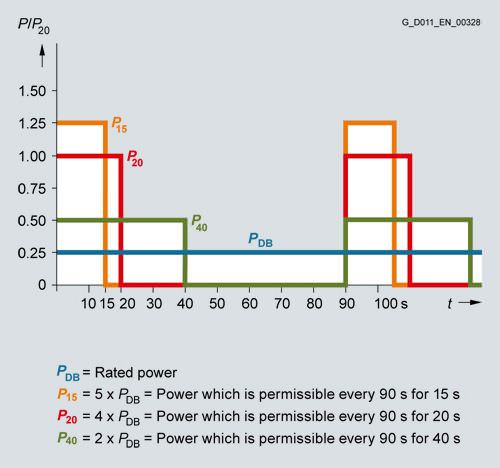
Load diagram for Braking Modules and braking resistors
Additional notes about possible duty cycles of the braking resistors and other engineering notes are included in the SINAMICS Low Voltage Engineering Manual.
L87
Insulation monitoring
An insulation monitor must be used if the converter is connected to an ungrounded line supply. The device monitors the entire galvanically coupled circuit for insulation faults.
An alarm is output in the event of a fault.
Notice: Only one insulation monitor can be used in each galvanically coupled network.
As there are different response strategies when a ground fault occurs in an ungrounded system, output relays of the insulation monitor are provided for integration in a plant-side control. It is also possible to integrate the outputs into the Cabinet Modules monitoring system on the plant side.
M06
Base 100 mm high, RAL 7022
The additional cabinet base allows larger bending radii for cables (cable inlet from below) and enables them to be routed within the cabinet base.
The cabinet base is supplied in RAL 7022 in all cases. A special paint finish is not available for the base. It is delivered completely assembled with the cabinet. The mounting height of the operator panel changes accordingly.
M07
Cable-marshalling space 200 mm high, RAL 7035
The cable-marshalling space is made of strong sheet steel and allows cables to be connected more flexibly (entry from below). It also allows routing of cables within the marshalling compartment. It is delivered completely assembled with the cabinet. The mounting height of the operator panel changes accordingly.
Notice: The cable-marshalling space is painted as standard with RAL 7035. If a special color is requested for the cabinet (option Y09), the cable-marshalling space is also painted in this color.
M21
IP21 degree of protection
Cabinet version in IP20, but with additional top or drip protection cover. This increases the cabinet height by 250 mm.
For transport reasons, the top or drip protection covers are delivered separately and must be fitted on site.
Notice: The top or drip protection covers are painted in RAL 7035 as standard. If a special color is requested for the cabinet (option Y09), the roof sections or drip protection panel are also painted in this color.
M23
IP23 degree of protection
Cabinet Modules with IP23 degree of protection are supplied with additional roof sections, plastic ventilation grilles, and a filter medium in the air inlet and outlet. This increases the cabinet height by 400 mm. The filter medium must be maintained according to the local environmental conditions. The covers provided with option M60 are also included in the scope of supply.
For transport reasons, the roof sections are delivered separately and must be fitted on site.
Notice: The roof sections are colored RAL 7035 as standard. If a special color is requested for the cabinet (option Y09), the roof section is also painted in this color. The molded plastic parts (e.g. ventilation grilles) are colored RAL 7035 and cannot be painted.
M26
Side panel mounted at the right
For side-by-side installation of Cabinet Modules from left to right, cabinets can be ordered ready-prepared at the factory for assembly on-site. If option M26 is ordered, the Cabinet Module is shipped with a side panel fitted on the right.
This side panel is essential for ensuring compliance with IP20 and higher degrees of protection.
M27
Side panel mounted at the left
For side-by-side installation of Cabinet Modules from right to left, cabinets can be ordered ready-prepared at the factory for assembly on-site. If option M27 is ordered, the Cabinet Module is shipped with a side panel fitted on the left.
This side panel is essential for ensuring compliance with IP20 and higher degrees of protection.
M43
IP43 degree of protection
Cabinet Modules with IP43 degree of protection are supplied with additional roof sections, plastic ventilation grilles, and a filter medium in the air inlet and outlet. This increases the cabinet height by 400 mm. The filter medium must be maintained according to the local environmental conditions.
For transport reasons, the roof sections are delivered separately and must be fitted on site.
Notice: The roof sections are colored RAL 7035 as standard. If a special color is requested for the cabinet (option Y09), the roof section is also painted in this color. The molded plastic parts (e.g. ventilation grilles) are colored RAL 7035 and cannot be painted.
M54
IP54 degree of protection
Cabinet Modules with IP54 degree of protection are supplied with additional roof sections, plastic ventilation grilles, and a filter medium in the air inlet and outlet, which ensures compliance with IP54 degree of protection. This increases the cabinet height by 400 mm.
The filters must be maintained according to the local environmental conditions.
For transport reasons, the roof sections are delivered separately and must be fitted on site.
Notice:
- The roof sections are colored RAL 7035 as standard. If a special color is requested for the cabinet (option Y09), the roof section is also painted in this color. The molded plastic parts (e.g. ventilation grilles) are colored RAL 7035 and cannot be painted.
- For units with IP54 degree of protection, it is important to observe the derating factor for output currents in relation to ambient temperature and installation altitude.
M59
Closed cabinet doors, air inlet from below through floor opening
If the Cabinet Modules are erected on a false floor or duct which forms part of a forced ventilation system, the modules can be ordered with closed cabinet doors. To ensure an adequate air inlet cross-section, the units are shipped without the standard base plates. In this case, the customer must ensure that no dirt/dust or moisture can enter the Cabinet Module. Cables must not be routed in such a way that they impede the flow of air through the cabinet floor opening. If the area beneath the Cabinet Modules can be accessed, the customer must provide touch protection.
M60
Additional touch protection
The Cabinet Modules are designed in accordance with BGV A3 as standard. With option M60, additional covers (out of reach) at accessible operator control and switching elements, are provided in the area of the AC and DC busbars and in front of the power unit.
M70
EMC shield bus
The EMC shield bus is used for the connection of line and motor shielded supply cables. The supplied EMC shield clamps provide a large surface area for the connection.
M80 to M87
DC busbar system
The correct DC busbar for the Cabinet Module must be ordered. This is fitted in the upper section of the Cabinet Modules and connects the Line Modules to the Motor Modules.
The busbar is dimensioned according to the load requirements and demand factor associated with operation of the individual drives, and according to the specific Cabinet Module layout. For this reason, the DC busbar is not supplied as standard, but must be ordered as an option.
When selecting busbars, it is important to ensure that the systems of adjacent Cabinet Modules are compatible with one another (refer to the table below and option selection matrix for the Cabinet Modules in question).
Where Cabinet Modules are ordered as a factory-assembled transport unit with option Y11, all busbars in the transport unit must be identical.
Option | DC busbar system, rated current IN | Number | Dimensions | Compatible with |
|---|---|---|---|---|
| A |
| mm |
|
M80 | 1170 | 1 | 60 × 10 | M83 |
M81 | 1500 | 1 | 80 × 10 | M84 and M86 |
M82 | 1840 | 1 | 100 × 10 | M85 and M87 |
M83 | 2150 | 2 | 60 × 10 | M80 |
M84 | 2730 | 2 | 80 × 10 | M81 and M86 |
M85 | 3320 | 2 | 100 × 10 | M82 and M87 |
M86 | 3720 | 3 | 80 × 10 | M81 and M84 |
M87 | 4480 | 3 | 100 × 10 | M82 and M85 |
The DC busbars are nickel-plated as standard and are available in different designs for a variety of current-carrying capacities. The scope of delivery also includes the jumpers required to link the busbar systems of individual Cabinet Modules.
M90
Crane transport assembly (top-mounted)
A top-mounted crane transport assembly can be ordered as an option for Cabinet Modules.
Depending on the width of the module, it consists of either transport eyebolts (width ≤ 800 mm) or transport rails (width > 800 mm).
When Cabinet Modules are ordered as factory-assembled transport units (option Y11), they are shipped with transport rails, i.e. option M90 is automatically included in the scope of delivery of option Y11 and does not need to be ordered separately.
N52
DC link fuses for the Basic Line Module
The Basic Line Modules do not have DC link fuses as standard.
If fuses are required, they can be ordered with option N52. The fuses are mounted on the connecting rail to the DC busbar in the cabinet rather than in the power unit.
DC link fuses are recommended when connecting Basic Line Modules in parallel.
P10
Measuring instrument for line values, mounted in the cabinet door
A measuring instrument with display, installed in the cabinet door of the Line Connection Module, for acquiring measured values of the power supply. In addition to these measured values, additional plant values (such as power and power factor, etc.) are calculated from the measured values using powerful, state- of- the art microprocessors.
The current transformers (option L41) are already included in the scope of delivery
P11
Measuring instrument for line values with PROFIBUS connection, mounted in the cabinet door
A measuring instrument with display, installed in the cabinet door of the Line Connection Module, for acquiring measured values of the power supply. In addition to these measured values, additional plant values (such as power and power factor, etc.) are calculated from the measured values using powerful, state- of- the art microprocessors. The measuring instrument has a PROFIBUS interface that permits a data transfer rate of up to 12 Mbit/s.
Запрос коммерческого предложения
Сообщение отправлено
В ближайшее время сообщение будет обработано.
Письмо с номером обращения отправлено на Ваш почтовый ящик.
Спасибо за то, что выбрали Первый ZIP!
Что-то пошло не так...
К сожалению, наша система расценила Ваше сообщение как спам.
Если это произошло по ошибке, пожалуйста, обратитесь к нам по электронной почте.
Приносим извинения за возможные неудобства.


по запрошенным товарам?


 Ответ от производителя может занять до 5 дней и более.


Beckhoff
Pepperl+Fuchs
Phoenix Contact
PILZ
Leuze Electronic
Endress+Hauser
Murr Elektronik
Schmersal