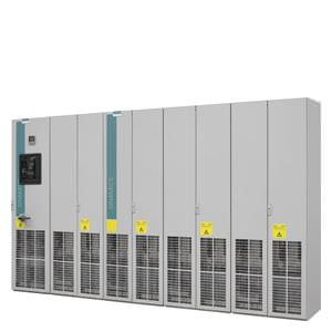
Customer terminal block -X55 Siemens
Обзор
Customer terminal block -X55 represents the interface to the I/O devices and marshals a range of cabinet-internal signals to a central terminal block module mounted in the lower part of the cabinet.
It can be used for Motor Modules in the chassis format as well as together with options K90 (CU320-2 DP Control Unit) or K95 (CU320-2 PN Control Unit) for Basic Line Modules, Smart Line Modules, Active Line Modules and Booksize Cabinet Kits.
Дизайн
To connect signal cables on the customer side, terminal block -X55 includes terminals -X122, -X132, -X41 and -X46 (terminals -X1 to -X4 are used inside the cabinet and are not available). As a consequence, depending on the version (with/without option K90 or K95) the following digital inputs/outputs and/or signals are available:
The customer terminal block -X55 includes: | Motor Modules chassis format | Line Modules | ||
|---|---|---|---|---|
| Without | with | Without | with |
CU320‑2 (K90/K95) | CU320‑2 (K90/K95) | |||
‑X122, ‑X132 | ||||
12 digital inputs DI | – | ✓ | – | ✓ |
8 bidirectional inputs/outputs (DI/DO) | – | ✓ | – | ✓ |
‑X41 | ||||
Connection, safety function Safe Torque Off/Safe Stop 1 | ✓ | ✓ | – 1) | – 1) |
Connection temperature sensor KTY84/PTC/Pt100 | ✓ | ✓ | – 1) | – 1) |
‑X46 | ||||
Connection, Safe Brake Adapter | ✓ | ✓ | – | – |
1) For Booksize Cabinet Kits, a connection is provided at the separate customer terminal block -X55.1 or -X55.2.
Pin assignment
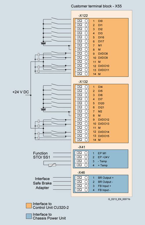
Terminal assignment of customer terminal block -X55
Terminal block -X55-X122 digital inputs/outputs | ||
|---|---|---|
Terminal | Designation 1) | Technical data |
1 | DI 0 | Voltage -30 V to +30 V DC Electrical isolation: Terminal M1 is the reference potential Level (including ripple): Input delay (typ.): |
2 | DI 1 | |
3 | DI 2 | |
4 | DI 3 | |
5 | DI 16 | |
6 | DI 17 | |
7 | M1 | Reference potential for terminals 1 to 6 |
8 | M | Ground |
9 | DI/DO 8 | As input: Voltage -30 V ... +30 V DC Level (including ripple): Fast inputs: 2) Input delay (typ.): As output: Voltage 24 V DC Output delay (typ./max.): 3) Switching frequency: |
10 | DI/DO 9 | |
11 | M | |
12 | DI/DO 10 | |
13 | DI/DO 11 | |
14 | M | |
Max. connectable cross-section: 1.5 mm2
1) DI: Digital input
DI/DO: bidirectional digital input/output
M: Electronics ground
M1: Reference ground.
2) Can be used as measuring probe input or input for the external zero mark
3) Data for: Ucc = 24 V; load 48 Ω; High (1) = 90 % Uout; Low (0) = 10 % Uout.
Terminal block -X55-X132 digital inputs/outputs | ||
|---|---|---|
Terminal | Designation 1) | Technical data |
1 | DI 4 | Voltage -30 V to +30 V DC Electrical isolation: Terminal M2 is the reference potential Level (including ripple): Input delay (typ.): |
2 | DI 5 | |
3 | DI 6 | |
4 | DI 7 | |
5 | DI 20 | |
6 | DI 21 | |
7 | M2 | Reference potential for terminals 1 to 6 |
8 | M | Ground |
9 | DI/DO 12 | As input: Voltage -30 V ... +30 V DC Level (including ripple): Fast inputs: 2) Input delay (typ.): As output: Voltage 24 V DC Output delay (typ./max.): 3) Switching frequency: |
10 | DI/DO 13 | |
11 | M | |
12 | DI/DO 14 | |
13 | DI/DO 15 | |
14 | M | |
Max. connectable cross-section: 1.5 mm2
1) DI: Digital input
DI/DO: bidirectional digital input/output
M: Electronics ground
M2: Reference ground.
2) Can be used as measuring probe input or input for the external zero mark
3) Data for: Ucc = 24 V; load 48 Ω; High (1) = 90 % Uout; Low (0) = 10 % Uout.
Terminal block -X55-X41 temperature sensor connection | ||
|---|---|---|
Terminal | Function | Technical data |
1 | EP M1 | Supply voltage 24 V DC (20.4 ... 28.8 V) Signal propagation times: The pulse inhibit function is only provided if Safety Integrated Basic Functions have been enabled. |
2 | EP +24 V | |
3 | -Temp | Temperature sensor connection for motor temperature sensing: |
4 | +Temp | |
Max. connectable cross-section: 2.5 mm2
Terminal block -X55-X46 brake control and monitoring | ||
|---|---|---|
Terminal | Function | Technical data |
1 | BR output + | The interface is used to connect the Safe Brake Adapter. |
2 | BR output - | |
3 | FB input + | |
4 | FB input - | |
Max. connectable cross-section: 1.5 mm2


 Ответ от производителя может занять до 5 дней и более.

