Converter Cabinet Units Siemens

Область применения
- Test bays
- Centrifuges
- Elevators and cranes
- Cross cutters and shears
- Conveyor belts with a high power demand and energy recovery
- Presses
- Cable winches
Дизайн
The SINAMICS S150 Converter Cabinet Units are characterized by their compact, modular and service-friendly design.
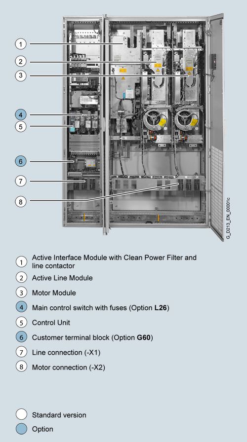
Design example of a SINAMICS S150 Converter Cabinet Unit

Basic design of a SINAMICS S150 Converter Cabinet Unit with a number of version-specific options
Varnished PCBs
The following drive units are equipped as standard with varnished PCBs:
- Chassis format units
- Control Units
- Sensor Modules
- Terminal Modules
- Advanced Operator Panel (AOP30)
The varnish coating on the modules protects the sensitive SMD components against corrosive gases, chemically active dust and moisture.
Nickel-plated busbars
All of the copper busbars used in the converter cabinets are nickel-plated in order to achieve the best possible immunity to environmental effects. Further, the bare copper connections do not have to be cleaned for customer connections.
Note: For technical reasons, some parts of the copper busbars are not nickel-plated for some of the options.
Degrees of protection
The EN 60529 standard covers the protection of electrical equipment by means of housings, covers or equivalent, and includes:
- Protection of persons against accidental contact with live or moving parts within the housing and protection of the equipment against the ingress of solid foreign matter (touch protection and protection against ingress of solid foreign bodies)
- Protection of the equipment against the ingress of water (water protection)
- Abbreviations for the internationally agreed degrees of protection
The degrees of protection are specified by abbreviations comprising the code letters IP and two digits.
Degree of protection | First code number (touch protection and protection against foreign bodies) | Second code number (protection of the equipment against the ingress of water) |
|---|---|---|
IP20 (Standard) | Protection against solid foreign bodies diameter ≥ 12.5 mm | No water protection |
IP21 (Option M21) | Protection against solid foreign bodies diameter ≥ 12.5 mm | Protected against drip water Vertically falling water drops shall not have a harmful effect. |
IP23 (Option M23) | Protection against solid foreign bodies diameter ≥ 12.5 mm | Protected against spray water Water sprayed on both sides of the vertical at an angle of up to 60° shall not have a harmful effect. |
IP43 (Option M43) | Protection against solid foreign bodies diameter ≥ 1 mm | Protected against spray water Water sprayed on both sides of the vertical at an angle of up to 60° shall not have a harmful effect. |
IP54 (Option M54) | Dust protected Ingress of dust is not totally prevented, but dust must not be allowed to enter in such quantities that the functioning or safety of the equipment isimpaired. | Protected against splash water Water splashing onto the enclosure from any direction shall not have a harmful effect. |
Характеристика
Derating data
SINAMICS S150 Converter Cabinet Units and the associated system components are rated for an ambient temperature of 40 °C and installation altitudes up to 2000 m above sea level.
For ambient temperatures > 40 °C the output current must be reduced. Ambient temperatures above 50 °C are not permissible.
At installation altitudes > 2000 m above sea level, it must be taken into consideration that with increasing height, the air pressure decreases and therefore the air density. As a consequence, the cooling efficiency and the insulation capacity of the air also decrease.
Due to the reduced cooling efficiency, it is necessary, on one hand, to reduce the ambient temperature and on the other hand, to lower heat loss in the converter cabinet unit by reducing the output current, whereby ambient temperatures lower than 40 °C may be offset to compensate.
The following table lists the permissible output currents as a function of the installation altitude and ambient temperature for the various degrees of protection. The specified values already include a permitted compensation in respect of installation altitude and ambient temperatures < 40 °C temperature at the air intake of the converter cabinet unit.
The values apply under the precondition that it is a guaranteed that the cooling air, as specified in the technical data, flows through the units as a result of the cabinet arrangement. As additional measure for installation altitudes from 2000 m up to 5000 m, an isolating transformer is required in order to reduce transient overvoltages according to EN 60664‑1. For additional information, please refer to the SINAMICS Low Voltage Engineering Manual.
Degree of protection | Installation altitude above sea level | Current derating factor (as a % of the rated current) | ||||||
|---|---|---|---|---|---|---|---|---|
m | 20 °C | 25 °C | 30 °C | 35 °C | 40 °C | 45 °C | 50 °C | |
IP20, IP21, IP23, IP43 | 0 ... 2000 | 100 % | 100 % | 100 % | 100 % | 100 % | 93.3 % | 86.7 % |
2001 ... 2500 | 100 % | 100 % | 100 % | 100 % | 96.3 % | |||
2501 ... 3000 | 100 % | 100 % | 100 % | 98.7 % | ||||
3001 ... 3500 | 100 % | 100 % | 100 % | |||||
3501 ... 4000 | 100 % | 100 % | 96.3 % | |||||
4001 ... 4500 | 100 % | 97.5 % | ||||||
4501 ... 5000 | 98.2 % | |||||||
IP54 | 0 ... 2000 | 100 % | 100 % | 100 % | 100 % | 93.3 % | 86.7 % | 80.0 % |
2001 ... 2500 | 100 % | 100 % | 100 % | 96.3 % | 89.8 % | |||
2501 ... 3000 | 100 % | 100 % | 98.7 % | 92.5 % | ||||
3001 ... 3500 | 100 % | 100 % | 94.7 % | |||||
3501 ... 4000 | 100 % | 96.3 % | 90.7 % | |||||
4001 ... 4500 | 97.5 % | 92.1 % | ||||||
4501 ... 5000 | 93.0 % | |||||||
Current-derating factors for SINAMICS S150 as a function of the ambient/air intake temperature, the installation altitude and the degree of protection.
Current derating as a function of pulse frequency
To reduce motor noise or to increase output frequency, the pulse frequency can be increased relative to the factory setting. When the pulse frequency is increased, the derating factor of the output current must be taken into account. This derating factor must be applied to the currents specified in the technical data.
For additional information, please refer to the SINAMICS Low Voltage Engineering Manual.
SINAMICS S150 Converter Cabinet Unit | Type rating | Output current | Derating factor at the pulse frequency | ||||
|---|---|---|---|---|---|---|---|
6SL3710-... | kW | A | 2.5 kHz | 4 kHz | 5 kHz | 7.5 kHz | 8 kHz |
380 … 480 V 3 AC | |||||||
7LE32-1AA3 | 110 | 210 | 95 % | 82 % | 74 % | 54 % | 50 % |
7LE32-6AA3 | 132 | 260 | 95 % | 83 % | 74 % | 54 % | 50 % |
7LE33-1AA3 | 160 | 310 | 97 % | 88 % | 78 % | 54 % | 50 % |
7LE33-8AA3 | 200 | 380 | 96 % | 87 % | 77 % | 54 % | 50 % |
7LE35-0AA3 | 250 | 490 | 94 % | 78 % | 71 % | 53 % | 50 % |
Derating factor of the output current as a function of the pulse frequency for units with a rated pulse frequency of 2 kHz
SINAMICS S150 Converter Cabinet Unit | Type rating | Output current | Derating factor at the pulse frequency | ||||
|---|---|---|---|---|---|---|---|
6SL3710-... | kW | A | 2.0 kHz | 2.5 kHz | 4 kHz | 5 kHz | 7.5 kHz |
380 … 480 V 3 AC | |||||||
7LE36-1AA3 | 315 | 605 | 83 % | 72 % | 64 % | 60 % | 40 % |
7LE37-5AA3 | 400 | 745 | 83 % | 72 % | 64 % | 60 % | 40 % |
7LE38-4AA3 | 450 | 840 | 87 % | 79 % | 64 % | 55 % | 40 % |
7LE41-0AA3 | 560 | 985 | 92 % | 87 % | 70 % | 60 % | 50 % |
7LE41-2AA3 | 710 | 1260 | 92 % | 87 % | 70 % | 60 % | 50 % |
7LE41-4AA3 | 800 | 1405 | 97 % | 95 % | 74 % | 60 % | 50 % |
500 … 690 V 3 AC | |||||||
7LG28-5AA3 | 75 | 85 | 93 % | 89 % | 71 % | 60 % | 40 % |
7LG31-0AA3 | 90 | 100 | 92 % | 88 % | 71 % | 60 % | 40 % |
7LG31-2AA3 | 110 | 120 | 92 % | 88 % | 71 % | 60 % | 40 % |
7LG31-5AA3 | 132 | 150 | 90 % | 84 % | 66 % | 55 % | 35 % |
7LG31-8AA3 | 160 | 175 | 92 % | 87 % | 70 % | 60 % | 40 % |
7LG32-2AA3 | 200 | 215 | 92 % | 87 % | 70 % | 60 % | 40 % |
7LG32-6AA3 | 250 | 260 | 92 % | 88 % | 71 % | 60 % | 40 % |
7LG33-3AA3 | 315 | 330 | 89 % | 82 % | 65 % | 55 % | 40 % |
7LG34-1AA3 | 400 | 410 | 89 % | 82 % | 65 % | 55 % | 35 % |
7LG34-7AA3 | 450 | 465 | 92 % | 87 % | 67 % | 55 % | 35 % |
7LG35-8AA3 | 560 | 575 | 91 % | 85 % | 64 % | 50 % | 35 % |
7LG37-4AA3 | 710 | 735 | 87 % | 79 % | 64 % | 55 % | 35 % |
7LG38-1AA3 | 800 | 810 | 97 % | 95 % | 71 % | 55 % | 35 % |
7LG38-8AA3 | 900 | 910 | 92 % | 87 % | 67 % | 55 % | 33 % |
7LG41-0AA3 | 1000 | 1025 | 91 % | 86 % | 64 % | 50 % | 30 % |
7LG41-3AA3 | 1200 | 1270 | 87 % | 79 % | 55 % | 40 % | 25 % |
Derating factor of the output current as a function of the pulse frequency for units with a rated pulse frequency of 1.25 kHz
The following table lists the maximum achievable output frequency as a function of the pulse frequency:
Pulse frequency | Max. achievable output frequency |
|---|---|
1.25 kHz | 100 Hz |
2.00 kHz | 160 Hz |
2.50 kHz | 200 Hz |
≥ 4.00 kHz | 300 Hz |
Overload capability
The SINAMICS S150 Converter Cabinet Units are equipped with an overload reserve to deal with breakaway torques, for example. If larger surge loads occur, this must be taken into account when configuring. In drives with overload requirements, the appropriate base load current must, therefore, be used as a basis for the required load.
The criterion for overload is that the drive is operated with its base load current before and after the overload occurs on the basis of a duty cycle duration of 300 s.
For short, repeating load cycles with significant load fluctuations within the load cycle, the appropriate sections in the SINAMICS Low Voltage Engineering Manual must be observed (as PDF file on the CD-ROM provided with the catalog).
The base load current for a low overload IL is the basis for a duty cycle of 110 % for 60 s or 150 % for 10 s.
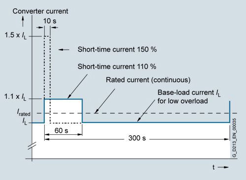
Low overload
The base load current for a high overload IH is the basis for a duty cycle of 150 % for 60 s or 160 % for 10 s.
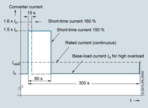
High overload
Функции
AOP30 Advanced Operator Panel

An Advanced Operator Panel (AOP30) is installed in the cabinet door of the converter for operation, monitoring and commissioning tasks.
The user is guided by interactive menus through the drive-commissioning screens. When commissioning the drive for the first time, only 6 motor parameters (which can be found on a motor rating plate) have to be entered on the AOP30. The control is then optimized automatically to fine-tune the converter to the motor.
The AOP30''s two-stage safety concept prevents unintentional or unauthorized changes to settings. Operation of the drive from the operator panel can be disabled by the keyboard lock so that only parameter values and process variables can be displayed on the operating panel. The OFF key is factory-set to active but can also be deactivated by the customer. A password can be used to prevent the unauthorized modification of converter parameters.
German, English, French, Italian, Spanish and Chinese are stored on the CU320-2 Control Unit CompactFlash card as operator panel languages. Russian, Polish and Czech are available in addition to these standard panel languages. These can be downloaded free of charge from the Internet under the following link:
http://support.automation.siemens.com/
Examples of plain-text displays at various phases of operation are shown below.
The First commissioning process is performed using the operator panel.

Only 6 motor parameters have to be entered: Power, speed, current, cos ϕ, voltage and frequency of the motor.
This information can be found on the motor rating plate, and must be entered into the screens on the display by following a short, menu-assisted procedure. The motor cooling method must also be specified.

The next screen contains the parameter values that are used to automatically optimize the control.

During operation, actual data are output on the display as absolute values, such as setpoint and actual values, or it is possible to parameterize up to three process variables as a quasi-analog bar display.
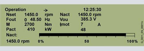
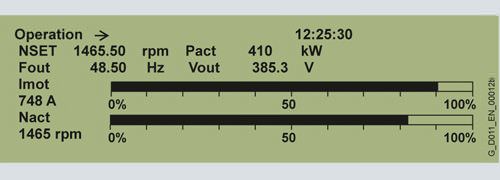
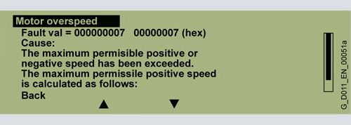
Any alarms which occur are signaled by flashing of the yellow ALARM LED, faults by the red FAULT LED which is then lit. There is also an indication of the cause displayed in plain text on the display''s status line (with counter/remedial measures).

Communication with higher-level control and customer terminal block
A PROFIBUS or PROFINET interface on the CU320-2 Control Unit is provided as standard as the customer control interface.
This interface can be used to connect the system to the higher-level controller using analog and digital signals, or to connect additional units.
The inputs and outputs available as standard can be optionally expanded by up to 2 TM31 Terminal Modules (refer to the description of options, option G60 or G61). To simplify configuration and commissioning of the drive, the TM31 Terminal Module can be preset to a variety of factory settings.
For additional information, please refer to the SINAMICS Low Voltage Engineering Manual.
Open-loop and closed-loop control functions
SINAMICS S150 has a high-dynamic vector control with speed and current control – with and without speed actual value feedback.
Software and protective functions
The software functions available as standard are described below:
Software and protective functions | Description |
|---|---|
Setpoint input | The setpoint can be input both internally and externally. It is applied internally as a fixed setpoint, motorized potentiometer setpoint or jog setpoint and externally via the communications interface or an analog input on the TM31 Terminal Module. The internal fixed setpoint and the motorized potentiometer setpoint can be switched over or adjusted using control commands from any interface. |
Motor identification | The automatic motor identification function makes commissioning faster and easier and optimizes closed-loop control of the drive. |
Ramp-function generator | A user-friendly ramp-function generator with separately adjustable ramp-up and ramp-down times, together with adjustable rounding times in the lower and upper speed ranges, allows the drive to be smoothly accelerated and braked. This results in a good speed control response and plays its role in reducing the stress on the mechanical system. The down ramps can be parameterized separately for quick stop. |
Vdc max controller | TheVdc max controller automatically prevents overvoltages in the DC link if the down ramp is too short, for example. This may also extend the set ramp-down time. |
Kinetic buffering (KIP) | For brief line supply failures, the kinetic energy of the rotating drive is used to buffer the DC link and therefore prevents fault trips. The drive converter remains operational as long as the drive can provide regenerative energy as a result of its motion and the DC link voltage does not drop below the shutdown threshold. When the line supply recovers within this time, the drive is again bumplessly accelerated up to its setpoint speed. |
Automatic restart | The automatic restart switches the drive on again when the power is restored after a power failure, and ramps up to the current speed setpoint. |
Flying restart | The flying restart function allows the converter to be switched to a motor that is still turning. |
Technology controller | Using the technology controller (PID controller) function module, level or flow controls and complex tension controls can be implemented, for example. The existing D component can act both on the system deviation as well as on the actual value (factory setting). The P, I, and D components are separately set. |
Free function blocks | Using the freely programmable function blocks, it is easy to implement logic and arithmetic functions for controlling the SINAMICS drive. The blocks can be programmed by means of an operator panel or the STARTER commissioning tool. |
Drive Control Chart (DCC) | Drive Control Chart (DCC) is an additional tool for the easy configuration of technological functions for SINAMICS. The block library contains a large selection of control, arithmetic and logic blocks as well as extensive open-loop and closed-loop control functions. The user-friendly DCC Editor enables easy graphics-based configuration, allows control loop structures to be clearly represented and provides a high degree of reusability of diagrams that have already been created. DCC is an add-on to the STARTER commissioning tool (→ Tools and engineering). |
I2t detection for motor protection | A motor model stored in the converter software calculates the motor temperature based on the current speed and load. More exact sensing of the temperature, which also takes into account the influence of the ambient temperature, is possible by means of direct temperature sensing using KTY84 sensors in the motor winding. |
Motor temperature evaluation | Motor protection by evaluating a KTY84, PTC or Pt100 temperature sensor. When a KTY84 temperature sensor is connected, the limit values can be set for alarm or shutdown. When a PTC thermistor is connected, the system reaction to triggering of the thermistor (alarm or shutdown) can be defined. |
Motor blocking protection | A blocked motor is detected and protected against thermal overloading by a fault trip. |
Power unit protection
Power unit protection | Description |
|---|---|
Ground fault monitoring at the output | A ground fault at the output end is detected by an aggregate current monitor and results in shutdown in grounded-neutral systems. |
Electronic short-circuit protection at the output | A short-circuit at the output (e.g. at the converter output terminals, in the motor cable or in the motor terminal box) is detected and the converter shuts down with a "fault". |
Thermal overload protection | An alarm is issued first when the overtemperature threshold responds. If the temperature continues to rise, the unit either shuts down or independently adjusts the pulse frequency or output current so that thermal load is reduced. Once the cause of the fault has been eliminated (e.g. cooling has been improved), the original operating values are automatically resumed. |
Safety Integrated functions
The integrated safety functions of SINAMICS provide highlyeffective application-oriented protection for personnel and machinery. The Safety Integrated functions are implemented electronically and therefore offer short response times in comparison to solutions with externally implemented monitoring functions.
The trend toward greater complexity and increasing modularity of machines is increasingly seeing a shift in safety functions away from the classical central safety functions (for example, shutdown of the complete machine using a main switch) and into the machine control system and the drives. Frequently, this also significantly increases the productivity. This is because, for instance, equipping times can be reduced and during these equipping times, depending on the machine type, other parts can still continue to produce.
Integrated safety functions act much faster than those of a conventional design. The safety of a machine is increased further with Safety Integrated. Furthermore, thanks to the faster method of operation, safety measures controlled by integrated safety systems are perceived as less of a hindrance by the machine operator, therefore significantly reducing the motivation to consciously bypass safety functions.
The safety functions in the device and communication via PROFIsafe have already been certified. This simplifies configuring the safety functions and especially the acceptance of the plant or system by an authorized testing body when compared to safety solutions made up of individual safety components.
Legal framework
Machine and plant builders must ensure that their machines or plants neither present risks due to electric shock, heat or radiation nor due to functional faults. In Europe, for example, compliance with the machinery directive is legally stipulated by the EU industrial safety directive.
In order to ensure compliance with this directive, it is recommended that the corresponding harmonized European standards are applied. This initiates the assumption of conformity and gives manufacturers and operators the legal security when complying with both national regulations and EU directives. The machine manufacturer uses the CE marking to document the compliance with all relevant directives and regulations in the free movement of goods.
Safety-related standards
Functional safety is specified in various standards. EN ISO 12100 and EN ISO 14121-1, for example, are concerned with the design and risk assessment of machines. EN 62061 (only applicable for electrical and electronic control systems) and EN ISO 13849-1 (previously EN 954-1) define the functional and safety-related requirements of control systems with relevance to safety.
The above-mentioned standards define different safety requirements that the machine has to satisfy in accordance with the risk, frequency of a dangerous situation, probability of occurrence and the opportunities for recognizing impending danger.
- EN 954‑1: Categories B, 1 … 4 (from the end of 2011 will be replaced by EN ISO 13849‑1)
- EN ISO 13849‑1: Performance Level PL a … e
- EN 62061: Safety Integrity Level SIL 1 … 3
Safety functions integrated in the drive with SINAMICS
The safety functions integrated in SINAMICS satisfy the equirements of
- Category 3 according to EN 954‑1 (from the end of 2011 will be replaced by EN ISO 13849‑1)
- Safety Integrity Level (SIL) 2 according to EN 61508
- Performance Level (PL) d according to EN ISO 13849‑1
In addition, the Safety Integrated functions of SINAMICS are generally certified by independent institutes. An up-to-date list of certified components is available on request from your local Siemens office.
Safety Basic Functions and Safety Extended Functions
The Safety Integrated functions of the SINAMICS drive system are subdivided into what are known as Safety Basic Functions and Safety Extended Functions (terminology according to IEC 61800‑5‑2):
- Basic Functions
- Safe Torque Off (STO)
- Safe Stop 1 (SS1, time-controlled)
- Safe Brake Control (SBC)
The Safety Basic functions are included in the standard scope of delivery of the drive and can be used without requiring any additional license. The user can activate these functions at any time. An encoder is not required for their use.
The Safety Basic Functions are controlled as follows:
- Via terminals at the Control Unit and at the power unit
- Via PROFIBUS or PROFINET with PROFIsafe profile (from version 3 (last position of the Order No. ≥ 3) and Drives SW Version V2.6 SP2)
- Safe Torque Off (STO)
- Safe Stop 1 (SS1, time-controlled and acceleration controlled)
- Safe Stop 2 (SS2)
- Safe Operating Stop (SOS)
- Safely-Limited Speed (SLS)
- Safe Speed Monitor (SSM)
- Safe Direction (SDI)
Safety Extended Functions require a safety license depending on the axes. Depending on the control, additional DRIVE-CliQ components are required.
Note: Extended Functions require a sine-cosine encoder and therefore a SMC20 Sensor Module Cabinet Mounted to evaluate the encoder signals (option K48).
The Safety Extended Functions are controlled as follows:
- Via the TM54F Terminal Module
- Via PROFIBUS or PROFINET with the PROFIsafe profile
The Safety Integrated functions currently available in SINAMICS S150 are subsequently described in more detail (terms as defined in IEC 61800‑5‑2):
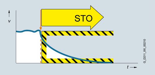
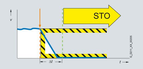
Safe Torque Off (STO)
Function description
This function prevents unexpected starting according to EN 60204-1 Section 5.4. Safe Torque Off disables the control of the power unit, preventing a potentially hazardous torque (corresponds to Stop Category 0 according to EN 60204-1). The drive is reliably torque-free. This state is monitored internally in the drive.
Under Extended Functions, STO can also be controlled via the TM54F Terminal Module or PROFIsafe.
Application, customer benefits
STO has the immediate effect that the drive cannot supply any torque-generating energy. STO can be used wherever the drive will naturally reach a standstill due to load torque or friction in a sufficiently short time or when "coasting down" of the drive will not have any relevance for safety.
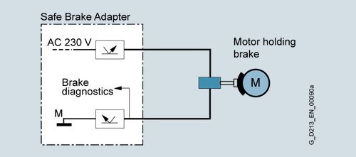
Safe Brake Control (SBC)
Function description
The Safe Brake Control SBC is used to control holding brakes, which are active in the no-current state, e.g. motor holding brakes (actuated using spring force). The brake is controlled through two channels in a safety-relevant fashion.
Safe Brake Control is executed when activating the operational brake control, Safe Torque Off function and when safety monitoring functions respond, which cause the power unit to be safely inhibited.
Note 1: The Safe Brake Control does not detect mechanical faults in the brake, for example worn brake pads.
Note 2: An additional Safe Brake Adapter (SBA) is required (option K88 or K89, for a description see SINAMICS S120 Chassis Format Units, Supplementary system components).
Application, customer benefits
In conjunction with STO and SS1, SBC can also be activated. After switching off the torque-generating energy, SBC offers the possibility to safely control a holding brake at the motor; for example, to prevent hanging/suspended axes from sagging.
Safe Stop 1 (SS1, time-controlled, without encoder; Basic Safety Function)
Function description
The Safe Stop 1 function can safely stop the drive in accordance with EN 60204-1, Stop Category 1. When the SS1 function is selected, the drive independently brakes along a quick stop ramp (OFF3) and Safe Torque Off and Safe Brake Control (if enabled) are activated when the selected safety delay time has expired.
Application, customer benefits
When activating the stop function, if the drive does not come quickly enough to a standstill as a result of the load torque, then it can be actively braked by the converter. As a result of this integrated fast brake function, frequently it is possible to eliminate mechanical brakes which wear, or to reduce the load on them. This means that maintenance costs and stress on the machine can be reduced.
Safe Stop 1 (SS1, time and acceleration controlled, with sine-cosine encoder; Extended Safety Function)
Function description
The Safe Stop 1 function can safely stop the drive in accordance with EN 60204-1, Stop Category 1. When the SS1 function is selected, the drive independently brakes along a quick stop ramp, the deceleration is monitored (OFF3) and Safe Torque Off and Safe Brake Control (if enabled) are automatically activated when the selected safety delay time has expired.
Application, customer benefits
When activating the stop function, if the drive does not come quickly enough to a standstill as a result of the load torque, then it can be actively braked by the converter. As a result of this integrated fast brake function, frequently it is possible to eliminate mechanical brakes which wear, or to reduce the load on them. This means that maintenance costs and stress on the machine can be reduced.
Safe Stop 2 (SS2, with sine-cosine encoder)
Function description
The Safe Stop 2 function can safely stop the drive in accordance with EN 60204-1, Stop Category 2. When the SS2 function is selected, the drive brakes autonomously along a quick stop ramp (OFF3). In contrast to SS1, the drive control remains operational afterwards, i.e. the motor can supply the full torque required to maintain the actual position. Standstill is safely monitored (Safe Operating Stop function, SOS).
Application, customer benefits
Just the same as for SS1, the drive is independently braked when the stop function is selected. Contrary to SS1, also at standstill, the drive can provide the full torque.
Safe Stop 1 (SS1) and Safe Stop 2 (SS2) with Safe Acceleration Monitor (SAM, with sine-cosine encoder)
For the Extended Functions Safe Stop 1 (SS1) and Safe Stop 2 (SS2) with SAM, during braking, the acceleration is safely monitored (SAM) in order to identify faults already during the braking phase.
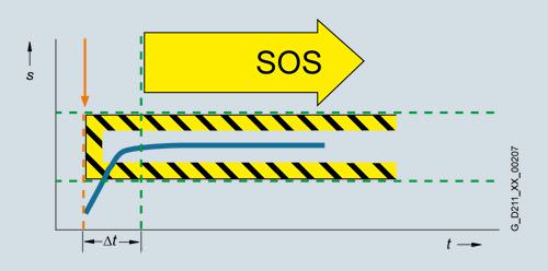
Safe Operating Stop (SOS, with sine-cosine encoder)
Function description
The Safe Operating Stop function constitutes safe standstill monitoring. The drive control remains in operation. The motor can therefore deliver the full torque to hold the current position. The actual position is reliably monitored. In contrast to safety functions SS1 and SS2, the speed setpoint is not influenced autonomously. After SOS has been selected, the higher-level control must bring the drive to a standstill within a parameterized safe time Δt and then hold the position setpoint. After the time Δt has expired, SOS is activated and monitored to ensure that the actual standstill position is not left.
Application, customer benefits
SOS is the ideal function for all those applications for which the machine or parts of the machine must be at a safe standstill for certain machining steps, but where the drive must also supply a holding torque.
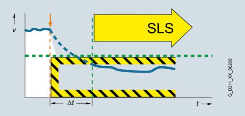
Safely-Limited Speed (SLS, with sine-cosine encoder)
Function description
Using the Safely-Limited Speed function, the drive is monitored against a parameterizable maximum velocity. Four different limit values can be activated. Just the same as for SOS, the speed setpoint is not independently influenced. After SLS has been selected, the higher-level control must bring the drive to below the selected velocity limit within a parameterizable time Δt.
Application, customer benefits
When setting-up many machines operating personnel must work on the machine as it rotates. This must either be done in steps, because the dangerous area must always be exited at each start, or alternatively, the operator works at the machine while it moves and is therefore exposed to an increased risk. When using the SLS function, a considerable amount of time can be saved – and it is still guaranteed that the operating personnel are safe. For this purpose, the drive velocity can be safely limited to a safe low level. The selectable wait time until SLS is activated allows the drive control to run-down the coordinated axes in a controlled fashion.
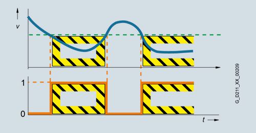
Safe Speed Monitor (SSM, with sine-cosine encoder)
Function description
The Safe Speed Monitor function supplies a safety feedback signal (high active) if the drive falls below a selectable velocity limit value. Contrary to the functions described above, there is no drive-based fault response when the limit value is exceeded.
Application, customer benefits
The safety SSM feedback signal can be used in a higher-level control for safety-relevant responses. The higher-level safety control can flexibly respond to the signal, depending on the particular situation, as there is no drive-based response when the limit value is exceeded. For example, using the SSM signal, a protective door can be released after a non-hazardous velocity is reached.
Safe Direction (SDI, with sine-cosine encoder)
Function description
The SDI function ensures that the drive can only rotate in the selected direction.
Deviation from the dir


 Ответ от производителя может занять до 5 дней и более.

