SINAMICS G120P Cabinet, 110 kW to 400 kW Siemens
Область применения
Variable-speed drives are ideal for all applications that involve moving, conveying, pumping, or compressing liquids or gases.
This means the following applications in particular:
- Pumps
- Fans
- Compressors
Обзор
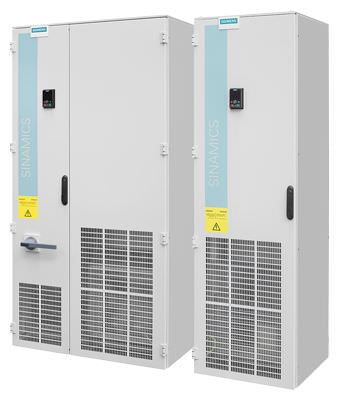
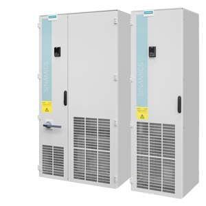
SINAMICS G120P Cabinet drive inverter cabinet units, versions A and C
With its SINAMICS G120P Cabinet drive inverter cabinet units, Siemens is offering a drive system on which all line-side and motor-side components as well as the Power Module are integrated into a specially designed cabinet enclosure. This design minimizes configuring and installation expenditure.
SINAMICS G120P Cabinet has been specially tailored to meet the requirements of drives for pumps, fans and compressors with quadratic load characteristic that have medium performance requirements with no regenerative feedback capability.
The control accuracy of the sensorless vector control is suitable for most applications, and additional actual speed value encoders are therefore superfluous.
SINAMICS G120P Cabinet offers an economic drive solution that can be matched to customer-specific requirements using a range of available components and options.
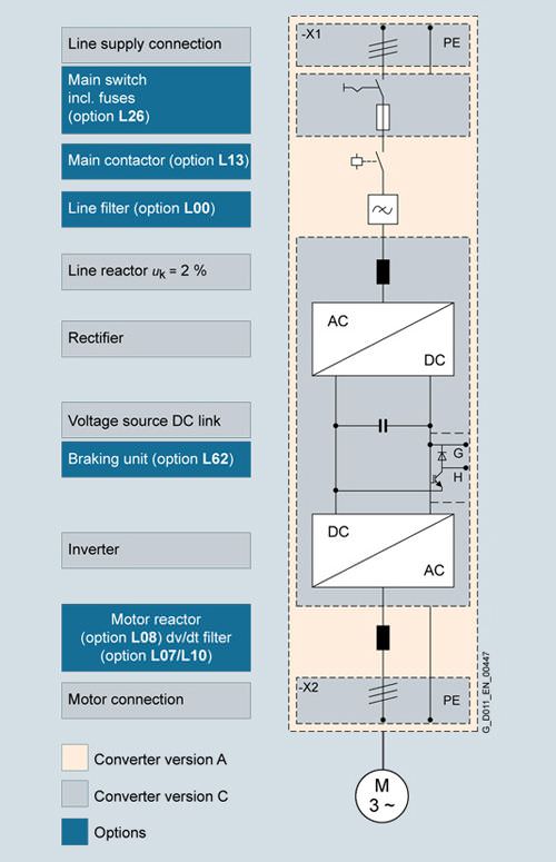
There are two versions of the drive inverter cabinet units:
- Version A
enables all optionally available line connection components, such as the main switch, main contactor, line fuses, line filter, motor-side components and additional monitoring devices to be installed - Version C
space-saving design with line reactor and optional main switch. This particularly slimline design can be used, for example, when line connection components are accommodated in a central low-voltage distribution panel (MCC) in the customer''s plant or system.
SINAMICS G120P Cabinet drive inverter cabinet units are available for the following voltages and outputs:
Line voltage | Output range |
|---|---|
380 ... 480 V 3 AC | 110 ... 400 kW |
The units have degree of protection IP20 as standard. They are optionally available with degrees of protection IP21, IP23, IP43 and IP54.
Дизайн
SINAMICS G120P Cabinet drive inverter cabinet units are characterized by their modular and service-friendly design.
A wide range of options is available depending on the cabinet version, which permits optimum adaptation of the drive system to the respective requirements (see section Options).
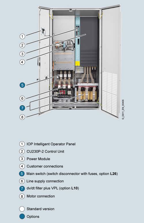
Example of design of a SINAMICS G120P Cabinet drive inverter cabinet unit, version A with a CU230P-2 Control Unit
Basic design of a SINAMICS G120P Cabinet drive inverter cabinet unit with several essential options
Coated modules
The following inverter components are equipped as standard with coated modules:
- Power Modules
- Control Units
- Intelligent Operator Panel IOP
The coating on the modules protects the sensitive SMD components against corrosive gases, chemically active dust and moisture.
Nickel-plated busbars
All of the busbars used in the inverter cabinet are nickel-plated in order to achieve the best possible immunity to environmental effects. Further, the bare copper connections do not have to be cleaned for customer connections.
Note:
For some options, for technical reasons, parts of the copper busbars cannot be nickel-plated.
Crane transport aid
The inverter cabinet units are supplied with a crane transport aid mounted on the top. In the case of single cabinets up to a width of 1200 mm, transport eyebolts are provided to transport the unit by crane. Transport rails are used with cabinet widths >1200 mm or for several cabinets (e.g. option L01). Rope spreaders should be used for low crane hook heights.
Degrees of protection of cabinet units
The EN 60529 standard covers the protection of electrical equipment by means of housings, covers or equivalent, and includes:
- Protection of persons against accidental contact with live or moving parts within the housing and protection of the equipment against the ingress of solid foreign matter (touch protection and protection against ingress of solid foreign bodies)
- Protection of the equipment against the ingress of water (water protection)
- Abbreviations for the internationally agreed degrees of protection
The degrees of protection are specified by abbreviations comprising the code letters IP and two digits.
Degrees of protection of the drive inverter cabinet unit | First digit
| Second digit
|
|---|---|---|
IP20 (standard) | Protected against solid foreign bodies, diameter ≥ 12.5 mm. | No water protection |
IP21 (option M21) | Protected against solid foreign bodies, diameter ≥ 12.5 mm. | Protected against drip water Vertically falling drip water shall not have a harmful effect. |
IP23 (option M23) | Protected against solid foreign bodies, diameter ≥ 12.5 mm. | Protected against spray water Water sprayed on both sides of the vertical at an angle of up to 60° shall not have a harmful effect. |
IP43 (option M43) | Protected against solid foreign bodies, diameter ≥ 1 mm. | Protected against spray water Water sprayed on both sides of the vertical at an angle of up to 60° shall not have a harmful effect. |
IP54 (option M54) | Dust protected. Ingress of dust is not totally prevented, but dust must not be allowed to enter in such quantities that the functioning or safety of the equipment is impaired. | Protected against splash water Water splashing onto the enclosure from any direction shall not have a harmful effect. |
Характеристика
Derating data
SINAMICS G120P Cabinet units and the associated system components are rated for an ambient temperature of 40 °C and installation altitudes up to 1000 m above sea level.
At ambient temperatures of > 40 °C, the output current must be reduced. Ambient temperatures above 50 °C are not permissible.
At installation altitudes > 1000 m above sea level, it must be taken into account that the air pressure, and therefore air density, decreases as the height increases. As a consequence, the cooling efficiency and the insulation capacity of the air also decrease.
Due to the reduced cooling efficiency, it is necessary, on the one hand, to reduce the ambient temperature, and on the other hand, to lower heat loss in the inverter cabinet unit by reducing the output current.
As additional measure for installation altitudes from 2000 m up to 4000 m, an isolating transformer is required in order to reduce transient overvoltages according to EN 60664‑1.
Automatic adjustment of pulse frequency
In the factory setting, the drive starts with a pulse frequency of 4 kHz and reduces the pulse frequency automatically to the associated required frequencies when loaded. When the load decreases, the pulse frequency is increased automatically up to 4 kHz. The values of the rated current apply to a pulse frequency of 2 kHz and an ambient temperature of 40 °C and are reached at any time by the automatic adaptation of the output pulse frequency.
Current derating as a function of installation altitude
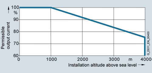
Permissible output current as a function of the installation altitude for SINAMICS G120P Cabinet units, frame size GX

Permissible output current as a function of the installation altitude for SINAMICS G120P Cabinet units, frame size HX
Note:
The connected motors and power elements must be considered separately.
Current derating as a function of ambient temperature

Permissible output current as a function of the ambient temperature
System operating voltage
The PM330 Power Modules supply a constant power over the full permissible range of line voltage.
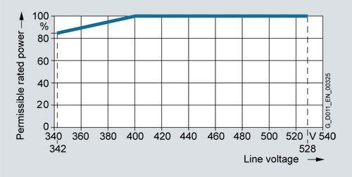
Rated power as a function of the line voltage
The constant power results in current derating as a function of the line voltage.
SINAMICS G120P Cabinet | Rated output current Irated at 380 ... 400 V | 380 V | 400 V | 415 V | 460 V | 480 V |
|---|---|---|---|---|---|---|
Type | A | % | % | % | % | % |
6SL3710-1PE32-1 . A0-Z | 205 | 100 | 100 | 95.9 | 83.5 | 78.0 |
6SL3710-1PE32-5 . A0-Z | 245 | 100 | 100 | 95.3 | 83.1 | 75.0 |
6SL3710-1PE33-0 . A0-Z | 300 | 100 | 100 | 96.6 | 86.2 | 81.6 |
6SL3710-1PE33-7 . A0-Z | 370 | 100 | 100 | 96.9 | 87.8 | 83.7 |
6SL3710-1PE34-6 . A0-Z | 460 | 100 | 100 | 96.4 | 85.4 | 80.6 |
6SL3710-1PE35-8 . A0-Z | 585 | 100 | 100 | 96.9 | 87.8 | 83.7 |
6SL3710-1PE36-6 . A0-Z | 655 | 100 | 100 | 96.4 | 85.4 | 80.6 |
6SL3710-1PE37-4 . A0-Z | 735 | 100 | 100 | 96.6 | 86.6 | 82.1 |
Operating ranges
An additional dimensioning aid is available for all inverters with a PM330 Power Module. The purpose of this aid is to ensure the constant reliable operation of the inverter, in particular with regard to service life expectancy.
The dimensioning aid clearly distinguishes between continuous operating ranges and short-time operating ranges. As a result, due consideration can be given to operating ranges when the plant is configured. For further details, please refer to the diagram below and the explanatory text.
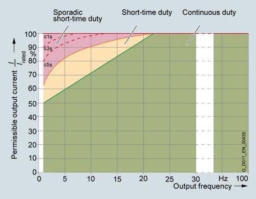
Continuous operation (green area) permissible.
Short-time operation (yellow area) permissible for 2 % of the total operating period without significant reduction in the inverter service life; no overload reaction triggered by the thermal monitoring model.
Sporadic short-time operation (red area) permissible for only very short, rare operating states lasting less than 0.1 % of the total operating period without significant reduction in the inverter service life; no overload reaction triggered by the thermal monitoring model on condition of compliance with the duty times specified in the diagram.
Overload capability
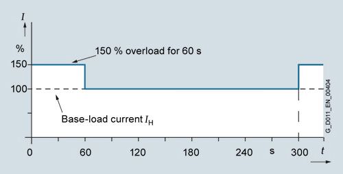
SINAMICS G120P Cabinet drive inverter cabinet units are equipped with an overload reserve to deal with breakaway torques, for example. If larger surge loads occur, this must be taken into account when configuring. In drives with overload requirements, the appropriate base-load current must, therefore, be used as a basis for the required load.
The unit can operate in two different duty cycles in the permissible continuous operating range shown in the diagram (green area). Depending on how the system is dimensioned, the relevant base-load current is effective as a rated quantity.
The criterion for overload is that the drive is operated with its base-load current before and after the overload occurs on the basis of a duty cycle duration of 300 s.
The base-load current for a low overload IL is the basis for a duty cycle of 110 % for 60 s or 135 % for 3 s.
The base-load current IH for a high overload is based on a duty cycle of 150 % for 60 s.
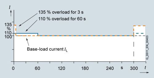
Overload capability, low overload
Overload capability, high overload
Функции
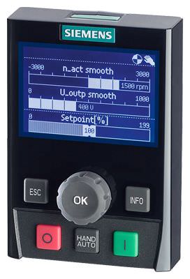
Intelligent Operator Panel IOP
The IOP (Intelligent Operator Panel) is mounted in the door of the cabinet units. It is used to operate and commission the drive system. The IOP is an extremely user-friendly, powerful operator panel.
The IOP supports both entry-level personnel and drive experts. Thanks to the large plain text display, the menu prompting and the application wizards, it is easy to perform commissioning. A drive can be essentially commissioned without having to use a printed parameter list – as the parameters are displayed in plain text, and explanatory help texts and the parameter filtering function are provided.
Application wizards interactively guide you when commissioning important applications such as pumps and fans. There is a basic commissioning wizard for general commissioning.
The drives are easily controlled manually using directly assigned buttons and the navigation wheel. The IOP has a dedicated switchover button to switch from automatic to manual mode.
The inverter can be diagnosed in a user-friendly fashion using the plain text display of faults and alarms. Help texts can be obtained by pressing the INFO button. Up to 2 process values can be displayed graphically or numerically on the status screen/status display. Process values can also be displayed in technological units.
The IOP supports standard commissioning of identical drives. For this purpose, a parameter list can be copied from an inverter into the IOP and downloaded into other drive units of the same type as required. This functionality is available only if a memory card is installed in the Control Unit.
The IOP supports the following languages 1): German, English, French, Italian, Spanish, Portuguese, Dutch, Swedish, Russian, Czech, Polish, Turkish, Finnish.
The operating temperature of the IOP is 0 ... 50 °C (32 ... 122 °F).
1) Further information is available at
http://support.automation.siemens.com/WW/view/en/67273266
Communication with higher-level control and customer terminal block
Depending on the selected CU230P‑2 Control Unit, the following interfaces for communication with the higher-level control system are provided:
- PROFINET, EtherNet/IP (option K96)
- PROFIBUS (option K97)
- USS/Modbus RTU/BACnet MS/TP, P1 protocol (option K98)
- CANopen (option K99)
The Control Unit can be connected to the higher-level control via its digital inputs and outputs.
Open-loop and closed-loop control functions
The inverter control contains a high-quality, sensorless vector control with speed and current controls as well as motor and inverter protection.
Software and protective functions
The software functions available as standard are described below:
Software and protective functions | Description |
|---|---|
Setpoint input | The setpoint can be input both internally and externally. It is applied internally as a fixed setpoint, motorized potentiometer setpoint or jog setpoint and externally via the communications interface or an analog input on the customer terminal block. The internal fixed setpoint and the motorized potentiometer setpoint can be switched over or adjusted using control commands from any interface. |
Motor identification | The automatic motor identification function makes commissioning faster and easier and optimizes closed-loop control of the drive. |
Ramp-function generator | An advanced ramp-function generator with separately adjustable ramping times, together with adjustable rounding times in the lower and upper speed ranges, allows the drive to be smoothly accelerated and braked. As a consequence, this avoids the drive train from being overloaded and reduces the stress on mechanical components. The down ramps can be parameterized separately for quick stop. |
Vdc max controller | The Vdc max controller automatically prevents overvoltages in the DC link if the set down ramp is too short, for example. This may also extend the set ramp-down time. |
Kinetic buffering (KIP) | In the event of supply voltage dips, the kinetic energy of the rotating drive is used to buffer the DC link so as to prevent fault trips. The inverter remains operational as long as the drive can provide regenerative energy as a result of its motion and the DC link voltage does not drop below the trip threshold. When the line supply recovers within this time, the drive is again accelerated up to its setpoint speed. |
Automatic restart1) | The automatic restart switches the drive on again when the power is restored after a power failure, and ramps up to the current speed setpoint. |
Flying restart1) | The "Flying restart" function allows the inverter to be switched to a motor that is still turning. |
Technology controller | The technology controllers (in the form of PID controllers) can be used to implement simple closed-loop control functions. A PID controller controls the motor speed as a process controller for temperature, pressure, air quality or fill levels. Three further PID controllers are freely programmable. The P, I, and D component can be disabled. |
Free function blocks | Using the freely programmable function blocks, it is easy to implement logic and arithmetic functions for controlling the SINAMICS G120P Cabinet unit. The blocks can be programmed by means of an operator panel or the STARTER commissioning tool. |
I²t detection for motor protection | A motor model stored in the inverter software calculates the motor temperature based on the current speed and load. More exact sensing of the temperature, which also takes into account the influence of the ambient temperature, is possible by means of direct temperature sensing using KTY sensors in the motor winding. |
Motor temperature evaluation | Motor protection by evaluating a temperature sensor of type KTY, PTC or bimetal NC contact. When a KTY sensor is connected, the limit values can be set for warning or shutdown. When a PTC thermistor is connected, the system reaction to triggering of the thermistor (alarm or shutdown) can be defined. |
Motor blocking protection | A blocked motor is detected and protected against thermal overloading by a fault trip. |
Multi-zone control | Closed-loop control of a zone with up to 3 sensors for pressure or temperature, or closed-loop control of two independent zones each with one sensor. |
Essential service mode | Special inverter operating mode that enhances the availability of the drive system in the event of a fire. |
Bypass 2) | When the setpoint is reached or a fault occurs, there is a changeover to mains operation. |
Cascade connection 2) | Load-dependent connection and disconnection of a maximum of three additional motors by the inverter in order to provide a largely constant output power. |
Hibernation mode | Startup or shutdown of the drive when the relevant value drops below an external setpoint or the internal PID controller setpoint |
1)Factory setting: not activated (can be parameterized)
2) This function requires an additional external circuit.
Power unit protection | Description |
|---|---|
Ground fault monitoring at output end | A ground fault at the output end is detected by a summation current monitor and results in shutdown in grounded systems. |
Electronic short-circuit protection at the output end | A short-circuit at the output end (e.g. at the inverter output terminals, in the motor cable or in the motor terminal box) is detected and the inverter shuts down with "fault". |
Thermal overload protection | An alarm is issued first when the overtemperature threshold responds. If the temperature rises further, the unit independently adjusts the pulse frequency or output current so that a reduction in the thermal load is achieved. Once the cause of the fault has been eliminated (e.g. cooling has been improved), the original operating values are automatically resumed. |
Конфигурация
Cable cross-sections and connections
The table below lists the recommended and maximum possible cable connections at the line and motor ends (versions A and C).
The recommended cross-sections are based on the specified fuses. They are applicable for 3-wire cables manufactured out of copper with PVC insulation, routed horizontally in air and a permissible wire temperature of 70 °C (e.g. Protodur NYY or NYCWY) for an ambient temperature of 40 °C and individual routing.
When the conditions differ from those specified above (cable routing, cable grouping, ambient temperature), the appropriate correction factors according to IEC 60364‑5‑52 must be taken into account.
Rated power | Inverter | Line supply connection | Motor connection | Cabinet grounding | |||||
|---|---|---|---|---|---|---|---|---|---|
| SINAMICS G120P Cabinet versions A and C | Recommended cross-section 1) | Maximum conductor cross-section | Fixing screw | Recommended cross-section 1) | Maximum conductor cross-section | Fixing screw | Maximum conductor cross-section | Fixing screw |
|
| IEC | IEC |
| IEC | IEC |
| IEC |
|
kW (hp) | 6SL3710‑ ... | mm2 | mm2 |
| mm2 | mm2 |
| mm2 |
|
380 ... 480 V 3 AC | |||||||||
110 | 1PE32-1 . A0-Z | 2 × 70 | 2 × 240 | M12 | 2 × 50 | 2 × 240 | M12 | 3 × 240 | M12 |
132 | 1PE32-5 . A0-Z | 2 × 95 | 2 × 70 | ||||||
160 | 1PE33-0 . A0-Z | 2 × 120 | 2 × 95 | ||||||
200 | 1PE33-7 . A0-Z | 2 × 120 | 2 × 95 | ||||||
250 | 1PE34-6 . A0-Z | 2 x 185 | 2 x 150 | ||||||
315 | 1PE35-8 . A0-Z | 2 x 240 | 4 × 240 | 2 x 185 | 4 x 240 | 6 x 240 | |||
355 | 1PE36-6 . A0-Z | 3 x 185 | 2 x 240 | ||||||
400 | 1PE37-4 . A0-Z | 3 x 185 | 2 x 240 | ||||||
1) The recommendations for the North American market in AWG or MCM should be taken from the appropriate NEC (National Electrical Code) or CEC (Canadian Electrical Code) standards.
Cable cross-sections required for connecting to the line supply and to motors
It is always recommended to use shielded - for higher power ratings - where possible symmetrical, 3-wire three-phase cables between the inverter and the motor, and where required, to connect several of these cables in parallel. There are essentially 2 reasons for this:
- Only then can the high IP55 degree of protection at the motor terminal box be easily achieved. The reason for this is that cables are routed into the terminal box through glands, and the number of possible glands is restricted by the terminal box geometry. Individual cables are less suitable in achieving this.
- With symmetrical 3-wire three-phase cables, the summed ampere-turns over the cable outer diameter are equal to zero. They can easily be routed in conductive, metal cable ducts or racks without any significant currents (ground current or leakage current) being induced in these conductive, metal connections. The danger of induced leakage currents, and thus of increased cable sheath losses, is significantly higher for single-wire cables.
The cable cross-section required depends on the current being conducted in the cable. The permissible current loading of cables is defined, for example, in IEC 60364‑5‑52. It depends on ambient conditions, such as temperature, but also on the routing method. It should be taken into account as to whether cables are routed individually and therefore relatively well ventilated, or whether groups of cables are routed together. In the latter case, the cables have significantly poorer ventilation and can therefore heat one another up more significantly. For the relevant correction factors applicable to these boundary conditions, please refer to IEC 60364‑5‑52.
The table below provides a guide to the recommended cross-sections (based on IEC 60364‑5‑52) for PVC-insulated, 3-wire copper and aluminum cables, a permissible conductor temperature of 70 °C (e.g. Protodur NYY or NYCWY), and an ambient temperature of 40 °C.
Current-carrying capacity according to IIEC 60364‑5‑52 at 40 °C
Cross-section 3-wire cable | Copper cable | Aluminum cable | ||
|---|---|---|---|---|
| Single routing | Several cables lying next to one another 1) | Single routing | Several cables lying next to one another 1) |
mm2 | A | A | A | A |
3 × 2,5 | 22 | 17 | 17 | 13 |
3 × 4,0 | 30 | 23 | 23 | 18 |
3 × 6,0 | 37 | 29 | 29 | 22 |
3 × 10 | 52 | 41 | 40 | 31 |
3 × 16 | 70 | 54 | 53 | 41 |
3 × 25 | 88 | 69 | 68 | 53 |
3 × 35 | 110 | 86 | 84 | 65 |
3 × 50 | 133 | 104 | 102 | 79 |
3 × 70 | 171 | 133 | 131 | 102 |
3 × 95 | 207 | 162 | 159 | 124 |
3 × 120 | 240 | 187 | 184 | 144 |
3 × 150 | 278 | 216 | 213 | 166 |
3 × 185 | 317 | 247 | 244 | 190 |
3 × 240 | 374 | 292 | 287 | 224 |
1)A maximum of 9 cables may be routed directly next to one another horizontally on a cable tray.
Cables must be connected in parallel for higher currents.
Note:
The recommendations for the North American market in AWG or MCM should be taken from the corresponding standards NEC (National Electrical Code) or CEC (Canadian Electrical Code).
Grounding and protective conductor cross-sections
The protective conductor must be dimensioned taking into account the following data:
- In the case of a ground fault, no impermissibly high contact voltages resulting from voltage drops on the PE conductor caused by the ground fault current may occur (< 50 V AC or < 120 V DC, IEC 61800‑5‑1, IEC 60364, IEC 60543).
- The PE conductor should not be excessively loaded by any ground fault current it carries.
- If it is possible for continuous currents to flow through the PE conductor when a fault occurs, the PE conductor cross-section must be dimensioned for this continuous current.
- The PE conductor cross-section should be selected according to IEC 60204‑1, IEC 60439‑1, IEC 60364.
Cross-section, line conductor | Minimum cross-section, external protective conductor |
|---|---|
mm2 | mm2 |
up to 16 | Minimum cross-section of external conductor |
16 ... 35 | 16 |
from 35 | At least half the cross-section of external conductor |
Note:
The recommendations for the North American market in AWG or MCM should be taken from the corresponding standards NEC (National Electrical Code) or CEC (Canadian Electrical Code).
Switchgear and motors are usually grounded separately via a local ground electrode. With this constellation, the ground fault current flows via the parallel ground connections and is divided. In spite of the relatively small protective conductor cross-sections used in accordance with the table above, no inadmissible touch voltages occur with this grounding system.
However, from experience gained with different grounding constellations, we recommend that the ground cable from the motor returns directly to the drive inverter. For EMC reasons and to prevent bearing currents – for higher power ratings – symmetrical, 3-wire, three-phase cables should be preferentially used instead of four-wire cables. For 3-wire cables, the protection or PE wire must be routed separately or arranged symmetrically in the motor cable. The symmetry of the PE conductor is achieved using a conductor surrounding all phase conductors or using a cable with a symmetrical arrangement of the three phase conductors and three ground conductors.
Through their high-speed controllers, the inverters limit the load current (motor and ground fault currents) to an rms value corresponding to the rated current. We therefore recommend the use of a PE conductor cross-section analogous to the phase conductor cross-section for grounding the control cabinet.
Особенности
- The inverters are exceptionally quiet and compact thanks to state-of-the-art IGBT power semiconductors, fan speed control as a function of temperature and reduced volumetric flow at the nominal working point.
- A rated switching frequency of 2 kHz, optimized pulse patterns and pulse frequency wobbling all help to reduce motor noise
- Individual modules and power components can be replaced quickly and easily, which ensures a higher level of plant availability. The design of replaceable components is based on the principle that they must be quick and easy to change. In addition, the "Spares on Web" Internet tool makes it easy to tailor the spare parts that are available to the task at hand (http://www.siemens.com/sow)
- Can be easily integrated in automation solutions by means of a standard communications interface on the Control Unit as well as a range of analog and digital interfaces
- Simple commissioning and parameterization via the IOP Intelligent Operator Panel or using the STARTER commissioning tool on a PC
- Preset software functions make it easier to tailor the inverter to the individual plant. For example, the key functions for controlling pumps are stored as a preprogrammed macro in the drive
- Regarding EMC, the units are sub-divided into various zones, and as a consequence, they are extremely insensitive to disturbances and are very reliable in operation. Detailed measurements and simulations have been conducted to determine the ideal positioning of air guidance and heat dissipation partitions
- Special measures used in the construction of the cabinets ensure that they remain mechanically durable over their entire lifecycle. All components, from individual parts to the ready-to-connect cabinet, undergo rigorous testing throughout the entire production process. This guarantees a high level of functional reliability during installation and commissioning, as well as in operation
Опции
Refer also to ordering examples for orders with order codes.
Available options | Order code | Version A | Version C |
|---|---|---|---|
Control Unit (it is essential to specify one of these four order codes) | |||
CU230P‑2 PN Control Unit | K96 | ✓ | ✓ |
CU230P‑2 DP Control Unit | K97 | ✓ | ✓ |
CU230P‑2 HVAC Control Unit | K98 | ✓ | ✓ |
CU230P‑2 CAN Control Unit | K99 | ✓ | ✓ |
Line-side options | |||
Use in the first environment to EN 61800‑3 | L00 | ✓ | – |
Clean Power version with integrated Line Harmonics Filter (380 ... 400 V ±10%) | L01 | ✓ 3) | – |
Main contactor | L13 | ✓ 3) | – |
Main switch, incl. fuses | L26 | ✓ | ✓ |
Motor-side options | |||
dv/dt filter compact plus VPL (Voltage Peak Limiter) | L07 | ✓ | – |
Motor reactor | L08 | ✓ | – |
dv/dt filter plus VPL (Voltage Peak Limiter) | L10 | ✓ | – |
Motor protection and safety functions | |||
EMERGENCY OFF pushbutton installed in the cabinet door | L45 | ✓ | – |
EMERGENCY OFF category 0, 24 VDC | L57 | ✓ 3) | – |
EMERGENCY STOP Category 1, 24 V DC 2) | L60 | ✓ 3) | – |
Thermistor motor protection unit (alarm) | L83 | ✓ 3) | – |
Thermistor motor protection unit (trip) | L84 | ✓ 3) | – |
Pt100 evaluation unit | L86 | ✓ 3) | – |
Degree of protection increase | |||
Degree of protection IP21 | M21 | ✓ 4) | ✓ |
Degree of protection IP23 | M23 | ✓ 3) | ✓ |
IP43 degree of protection | M43 | ✓ 3) | ✓ |
Degree of protection IP54 | M54 | ✓ 3) | ✓ |
Mechanical options | |||
Base 100 mm high, RAL 7035 | M06 | ✓ | ✓ |
Cable compartment 200 mm high, RAL 7035 | M07 | ✓ | ✓ |
Other options | |||
Provision of a cabinet-internal 230 V AC auxiliary power supply | Запрос коммерческого предложения× Сообщение отправлено× В ближайшее время сообщение будет обработано. Письмо с номером обращения отправлено на Ваш почтовый ящик. Спасибо за то, что выбрали Первый ZIP! Что-то пошло не так...× К сожалению, наша система расценила Ваше сообщение как спам. Если это произошло по ошибке, пожалуйста, обратитесь к нам по электронной почте. Приносим извинения за возможные неудобства.  Вы отправляете нам запрос  Если у нас есть прайс-лист, мы отправляем Вам ответ в течение дня. А если у нас нет прайс-листа по запрошенным товарам?     Если у нас нет прайс-листа, мы отправляем запрос производителю.  Ответ от производителя может занять до 5 дней и более. Ответ от производителя может занять до 5 дней и более.  Запрос производителю мы отправляем только для конечных потребителей.  Торгующим организациям коммерческие предложения предоставляются только по прайсовым позициям: Siemens Beckhoff Pepperl+Fuchs Phoenix Contact PILZ Turck Leuze Electronic Endress+Hauser Murr Elektronik Schmersal | ||