ARPEX ARC-8/-10 series Siemens
Область применения
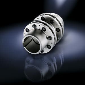
ARPEX couplings of the ARC-8 and ARC-10 series are outputand speed-optimized coupling solutions. Power transmission is by means of patented conical screw connections and plate packs of the octagonal and decagonal types. Torques of between 8.5 and 1450 kNm can be transmitted at a permitted angular misalignment of 0.2° to 0.4°. The closed flange shape and a compact construction permit high peripheral speeds and high speeds. On most types, the intermediate spacer can be radially fitted without moving the connected units.
Main areas of application for the ARC-8/-10 series:
- Paper-making machines
- Printing machines
- Compressors
- Fans and blowers
- Generators
- Presses
- Conveyors
- Crane systems
- Pumps
- Mills
- Rotary furnaces
- Stirrers
Обзор

Coupling can be designed for potentially explosive environments in accordance with 94/9/EC.
Дизайн
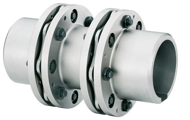
The classic design of an ARPEX coupling of the ARC-8/-10 series type NEN is shown in the following illustration. The plate packs are bolted alternately between the flanges of the coupling hubs and the intermediate spacer. Conical screw connections are used for fastening. The intermediate spacer lengths are variably designed according to customer specifications.
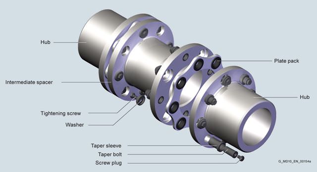
Design of an ARPEX coupling, ARC-8/-10 series, type NEN
Variants of the ARPEX coupling, ARC-8/-10 series
Types | |
|---|---|
NEN | Variant with intermediate spacer machined on all sides, length variable |
NHN | Variant with unmachined intermediate spacer, length variable |
BUB | Compact variant with split intermediate spacer for short shaft distances |
MFEFM | Variant with preassembled intermediate unit and machined intermediate spacer, length variable |
MFHFM | Variant with preassembled intermediate unit and unmachined intermediate spacer, length variable |
The coupling parts of the ARPEX ARC-8/-10 series with the exception of the H spacers have been machined on all sides. These are delivered with unmachined and primed spacer tube.
Further application-specific coupling types are available in selection module x.CAT at www.flender.com . Dimension sheets and further information are available on request.
Особенности
ARPEX couplings of the ARC-8/-10 series are outstanding for their robust construction. They have been optimized for high torques combined with high speeds. The patented conical screw connection ensures reliable torque transmission by a true positive fit and is designed to be extremely easy to fit. Couplings can be designed for potentially explosive environments in accordance with 94/9/EC.
Технические данные
Power ratings
Size | Rated torque | Maximum torque | Overload torque | Fatique torque | Maximum speed | Maximum permitted shaft misalignment | Torsional stiffness | ||||||||
|---|---|---|---|---|---|---|---|---|---|---|---|---|---|---|---|
TKN | TKmax | TKOL | TKW | nKmax | ±ΔKa | ±ΔKw | ±ΔKr | CTdyn | |||||||
NEN | BUB | MFEFM | NEN | NHN | BUB | MFEFM | MFHFM | ||||||||
S = 1000 mm | S = 1000 mm | Smin | S = 1000 mm | Smin | S = 1000 mm | ||||||||||
kNm | kNm | kNm | kNm | rpm | mm | mm | mm | mm | MNm/rad | MNm/rad | MNm/rad | MNm/rad | MNm/rad | ||
225-8 | 8.5 | 17 | 25.5 | 4.25 | 8500 | 1.94 | 0.4° | 6.87 | 0.96 | 6.53 | 3.1 | 0.9368 | 3.0 | 3.1 | 0.9748 |
255-8 | 12.7 | 25 | 38.1 | 6.35 | 7500 | 2.32 | 6.86 | 1.10 | 6.51 | 3.8 | 1.2778 | 3.7 | 3.8 | 1.3295 | |
270-8 | 16.5 | 33 | 49.5 | 8.25 | 7000 | 2.40 | 6.88 | 1.10 | 6.52 | 5.4 | 1.7339 | 5.1 | 5.4 | 1.8072 | |
295-8 | 23 | 46 | 69 | 11.5 | 6500 | 2.62 | 6.86 | 1.17 | 6.44 | 7.1 | 2.6134 | 6.7 | 7.1 | 2.7358 | |
325-8 | 33 | 66 | 99 | 16.5 | 6000 | 2.60 | 6.84 | 1.38 | 6.34 | 9.6 | 3.9537 | 9.4 | 9.6 | 4.1715 | |
355-8 | 45 | 90 | 135 | 22.5 | 5500 | 2.88 | 6.83 | 1.42 | 6.28 | 12.8 | 5.6093 | 12.5 | 12.8 | 5.9339 | |
385-8 | 56 | 112 | 168 | 28 | 5000 | 3.12 | 6.81 | 1.63 | 6.22 | 17.8 | 7.8517 | 17.0 | 17.8 | 8.3555 | |
420-8 | 70 | 140 | 210 | 35 | 4500 | 3.46 | 6.79 | 1.78 | 6.14 | 22.9 | 10.8175 | 21.9 | 22.9 | 11.5763 | |
455-8 | 88 | 176 | 264 | 44 | 4200 | 4.02 | 6.78 | 1.89 | 6.11 | 30.0 | 14.2794 | 28.2 | 30.0 | 15.2998 | |
505-8 | 120 | 240 | 360 | 60 | 3800 | 4.28 | 6.77 | 2.41 | 6.04 | 40.2 | 20.9046 | 36.4 | 40.2 | 22.4421 | |
545-8 | 165 | 330 | 495 | 82.5 | 3500 | 4.48 | 6.75 | 2.67 | 5.98 | 50.4 | 28.7428 | 45.0 | 50.4 | 30.7848 | |
595-8 | 210 | 420 | 630 | 105 | 3200 | 4.86 | 6.73 | 2.88 | 5.89 | 67.8 | 39.5343 | 59.5 | 67.8 | 42.5997 | |
630-8 | 260 | 520 | 780 | 130 | 3000 | 4.98 | 0.3° | 4.93 | 2.10 | 4.14 | 61.8 | 42.6162 | 61.2 | 61.8 | 46.3697 |
700-8 | 340 | 680 | 1020 | 170 | 2700 | 5.78 | 4.91 | 2.38 | 4.06 | 84.9 | 60.2135 | 83.1 | 84.9 | 65.8083 | |
S = 1500 mm | S = 1500 mm | S = 1500 mm | S = 1500 mm | ||||||||||||
630-10 | 340 | 680 | 1020 | 170 | 3000 | 3.04 | 0.2° | 5.03 | 1.40 | 4.50 | 94.6 | 46.9832 | 94.4 | 94.6 | 50.5520 |
700-10 | 430 | 860 | 1290 | 215 | 2700 | 3.60 | 5.02 | 1.58 | 4.45 | 135 | 72.3106 | 132 | 135 | 77.9729 | |
760-10 | 550 | 1100 | 1650 | 275 | 2500 | 3.70 | 4.98 | 1.60 | 4.30 | 173 | 91.7589 | 180 | 173 | 101.228 | |
860-10 | 770 | 1540 | 2310 | 385 | 2200 | 4.82 | 4.95 | 1.86 | 4.21 | 244 | 145.230 | 245 | 244 | 160.422 | |
950-10 | 1050 | 2100 | 3150 | 525 | 2000 | 5.40 | 4.91 | 1.92 | 4.09 | 325 | 204.443 | 338 | 325 | 227.957 | |
1035-10 | 1450 | 2900 | 4350 | 725 | 1850 | 5.78 | 4.88 | 1.95 | 3.97 | 426 | 292.140 | 455 | 426 | 326.930 | |
The permitted shaft misalignments ΔKa, ΔKr and ΔKw are maximum values and must not occur at the same time (see following table).
The specified, permitted shaft misalignment ΔKr for types NEN/NHN and MFEFM/MFHFM applies to a shaft distance of S = 1000 mm (ARC-8) or S = 1500 mm (ARC-10).
The permitted shaft misalignment ΔKr for types NEN and NHN is calculated as follows: ΔKr = (S – S1) · tan(ΔKw).
The permitted shaft misalignment ΔKr for types MFEFM and
MFHFM is calculated as follows:
ΔKr = (S – S1 – 2 · BF) · tan(ΔKw).
The values for torsional stiffness apply to the complete coupling. In the case of types NHN and MFHFM to a coupling with shaft distance S = 1000 mm (ARC-8) or S = 1500 mm (ARC-10). The torsional stiffness of the plate packs applies to the rated coupling torque TKN. To determine the torsional stiffness for a specific operating point, e.g. for calculating torsional vibration, the manufacturer must be consulted.
TKmax permitted only five times per hour.
Permitted shaft misalignments
Size | Permitted angular misalignment ±ΔKw | ||||
|---|---|---|---|---|---|
0.0° | 0.1° | 0.2° | 0.3° | 0.4° | |
Permitted axial misalignment ±ΔKa in mm | |||||
225-8 | 1.94 | 1.46 | 0.97 | 0.48 | 0.00 |
255-8 | 2.32 | 1.74 | 1.16 | 0.58 | 0.00 |
270-8 | 2.40 | 1.80 | 1.20 | 0.60 | 0.00 |
295-8 | 2.62 | 1.96 | 1.31 | 0.66 | 0.00 |
325-8 | 2.60 | 1.95 | 1.30 | 0.65 | 0.00 |
355-8 | 2.88 | 2.16 | 1.44 | 0.72 | 0.00 |
385-8 | 3.12 | 2.34 | 1.56 | 0.78 | 0.00 |
420-8 | 3.46 | 2.59 | 1.73 | 0.86 | 0.00 |
455-8 | 4.02 | 3.01 | 2.01 | 1.00 | 0.00 |
505-8 | 4.28 | 3.21 | 2.14 | 1.07 | 0.00 |
545-8 | 4.48 | 3.36 | 2.24 | 1.12 | 0.00 |
595-8 | 4.86 | 3.65 | 2.43 | 1.22 | 0.00 |
630-8 | 4.98 | 3.32 | 1.66 | 0.00 | |
700-8 | 5.78 | 3.85 | 1.93 | 0.00 | |
630-10 | 3.04 | 1.52 | 0.00 | ||
700-10 | 3.60 | 1.80 | 0.00 | ||
760-10 | 3.70 | 1.85 | 0.00 | ||
860-10 | 4.82 | 2.41 | 0.00 | ||
950-10 | 5.40 | 2.70 | 0.00 | ||
1035-10 | 5.78 | 2.89 | 0.00 | ||


 Ответ от производителя может занять до 5 дней и более.

