Safety Integrated Siemens
Обзор
Legal framework
Machine manufacturers and manufacturing plants must ensure that their machines or plants cannot cause danger due to malfunctions in addition to the general risks of electric shock, heat or radiation.
In Europe, for example, compliance with the machinery directive is required by law by the EC occupational health and safety directive. In order to ensure compliance with this directive, it is recommended that the corresponding harmonized European standards are applied. This triggers the "assumption of conformity" and gives manufacturers and operators the legal security in terms of compliance with both national regulations and EU directives. The machine manufacturer uses the CE marking to document the compliance with all relevant directives and regulations in the free movement of goods.
Safety-related standards
Functional safety is specified in various standards. For example, EN ISO 12100 specifies standards pertaining to machine safety (risk assessment and risk reduction). IEC 61508 specifies basic requirements for electronic and programmable safety-related systems. EN 62061 (only applicable for electrical and electronic control systems) and EN ISO 13849‑1, which has replaced EN 954‑1, define the functional and safety-related requirements of safety-oriented control systems.
The above-mentioned standards define different safety requirements that the machine has to satisfy in accordance with the risk, frequency of a dangerous situation, probability of occurrence and the opportunities for recognizing impending danger.
- EN ISO 13849‑1: Performance Level PL a … e
- EN 62061: Safety Integrity Level SIL 1 … 3
Trend toward integrated safety systems
The trend toward greater complexity and higher modularity of machines has seen a shift in safety functions away from the classical central safety functions (for example, shutdown of the complete machine using a main disconnecting means) and into the machine control system and the drives. This is often accompanied by a significant increase in productivity because the equipping times are shortened. Depending on the type of machine, it may even be possible to continue manufacturing other parts while equipping is in progress.
Integrated safety functions act much faster than those of a conventional design. The safety of a machine is increased further with Safety Integrated. Furthermore, thanks to the faster method of operation, safety measures controlled by integrated safety systems are perceived as less of a hindrance by the machine operator, therefore significantly reducing the motivation to consciously bypass safety functions.
Функции
Safety functions integral to the SINAMICS drives
SINAMICS drives are characterized by a large number of integrated safety functions. In combination with the sensors and safety control required for the safety functionality, they ensure that highly-effective protection for persons and machines is implemented in a practice-oriented manner.
They fulfill the following equipment requirements:
- SIL 2 according to IEC 61508
- PL d and Category 3 according to EN ISO 13849‑1
The Safety Integrated functions of SINAMICS drives are certified by independent institutions. You can obtain the corresponding test certificates and manufacturer''s declarations from your Siemens contacts.
The integrated safety functions that are currently available in the SINAMICS drive system are described below. The functional safety of all of the functions satisfies the requirements defined in the international standard IEC 61800‑5‑2 for variable-speed drive systems.
The safety functions integrated into the SINAMICS drive system can be roughly divided into four categories:
- Functions for safely stopping a drive
- Safe Torque Off (STO)
- Safe Stop 1 (SS1)
- Safe Stop 2 (SS2)
- Safe Operating Stop (SOS)
- Safe Brake Control (SBC)
- Safe Brake Test (SBT) (this function exceeds the scope of IEC 61800‑5‑2)
- Safely-Limited Speed (SLS)
- Safe Speed Monitor (SSM)
- Safe Direction (SDI)
- Safely Limited Position (SLP)
- Safe Position (SP) (this function exceeds the scope of IEC 61800‑5‑2)
The Safety Integrated Function Manual contains detailed information about the safety functions.
http://support.automation.siemens.com/WW/view/en/99668646
Further manuals pertaining to Safety Integrated in drive systems can be found on the Internet at
http://support.automation.siemens.com/WW/view/en/21901735/133300
Further information about Safety Integrated can be found on the Internet at
www.siemens.com/safety-drives
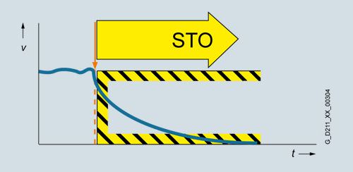
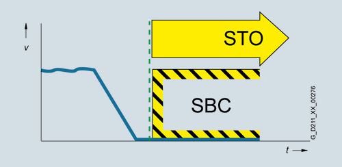
Safe Torque Off (STO)
The STO function is the most common and basic drive-integrated safety function. It ensures that no torque-generating energy can continue to affect a motor and prevents unintentional start-ups.
Activation
This function is a mechanism that prevents the drive from restarting unexpectedly, in accordance with EN 60204-1, Section 5.4. Safe Torque Off suppresses the drive pulses (corresponds to Stop Category 0 of EN 60204-1). The drive is reliably torque-free. This state is monitored internally in the drive.
Application
STO has the immediate effect that the drive cannot supply any torque-generating energy. STO can be used wherever the drive will naturally reach a standstill due to load torque or friction in a sufficiently short time or when "coasting down" of the drive will not have any relevance for safety.
STO makes it possible for persons to work safely when the protective door is open (restart interlock) and is used on machines/installations with moving axes, e.g. on handling or conveyor systems.
Customer benefits
The advantage of the integrated STO safety function compared to standard safety technology using electromechanical switchgear is the elimination of separate components and the effort that would be required to wire and service them. Because of the fast electronic switching times, the function provides a shorter reaction time than the conventional solution comprising electromechanical components.
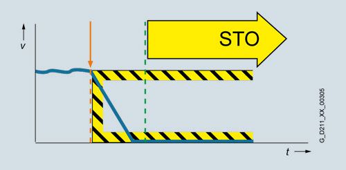
Safe Stop 1 (SS1)
The SS1 function causes a motor to stop rapidly and safely and switches the motor to torque-free mode after coming to a standstill, i.e. STO is activated.
Activation
The SS1 function can safely stop the drive in accordance with EN 60204‑1, Stop Category 1. When the SS1 function is selected, the drive brakes autonomously along a quick-stop ramp and automatically activates the Safe Torque Off and Safe Brake Control functions (if configured) when the parameterized safety delay time expires.
Application
The SS1 function is used when, in the event of a safety-relevant incident, the drive must stop as quickly as possible with a subsequent transition into the STO state (e.g. EMERGENCY STOP). It is thus used to bring large centrifugal masses to a stop as quickly as possible for the safety of the operating personnel, or to brake motors at high speeds as quickly as possible. Examples of typical applications are saws, grinding machine spindles, centrifuges, winders and storage and retrieval machines.
Customer benefits
The targeted stopping of a drive by means of SS1 reduces the risk of danger, increases the productivity of a machine, and allows the safety clearances in a machine to be reduced. The principle is to bring the drive actively to a standstill, compared with just using the STO function. Complex mechanical brakes that are susceptible to wear are not normally required to brake the motor.
Safe Stop 2 (SS2)
The SS2 function brings the motor to a standstill quickly and safely and then activates the SOS function once the motor has stopped.
Activation
The Safe Stop 2 function can safely stop the drive in accordance with EN 60204‑1, Stop Category 2. When the SS2 function is selected, the drive brakes autonomously along a quick stop ramp. In contrast to SS1, the drive control remains operational afterwards, i.e. the motor can supply the full torque required to maintain zero speed. Standstill is safely monitored (Safe Operating Stop function).
Application
As with SS1, the SS2 function ensures the quickest possible deceleration of the motor. However, the motor power is not switched off. Instead, a control system prevents it from leaving the standstill position – even if it is affected by external forces. Typical applications for SS2 include machine tools, for example.
Customer benefits
The SS2 function ensures a rapid axis stop. Because the control remains active, after the safety function is deselected, productive operation can continue without referencing. This ensures short setup and standstill times and high productivity.
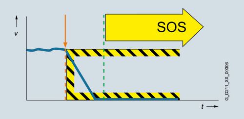
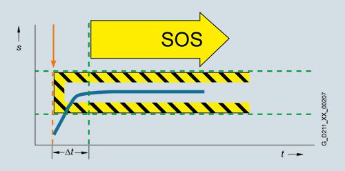
Safe Operating Stop (SOS)
With the SOS function, the stopped motor is held in position and monitored by drive control.
Activation
The SOS function constitutes safe standstill monitoring. The drive control remains in operation. The motor can therefore deliver the full torque to hold the current position. The actual position is reliably monitored. In contrast to safety functions SS1 and SS2, the speed setpoint is not influenced autonomously. After SOS has been activated, the higher-level control must bring the drive to a standstill within a parameterized time and then hold the position setpoint.
Application
SOS is an ideal solution for all those applications for which the machine or parts of the machine must be at a safe standstill for certain steps, but the drive must also supply a holding torque. It is ensured that despite counter torque the drive remains in its current position. In contrast to SS1 and SS2, the drive does not brake autonomously in this case. It expects the higher-level controller to ramp down the relevant axes as a coordinated group within an adjustable delay time. This can be used to prevent any damage to the machine or product. Typical applications for SOS include winders, converting and packaging machines and machine tools.
Customer benefits
No mechanical components are necessary to keep the axis in position despite any counterforce that may occur. Due to the short switching times and the fact that the drive control always remains active, setup and downtimes are reduced. Recalibration of the axis after exiting the SOS function is not necessary. The axis can immediately be moved again after deactivation of the SOS function.
Safe Brake Control (SBC)
The SBC function permits the safe control of a holding brake. SBC is always activated in parallel with STO.
Activation
A holding brake which is active in a de-energized state is controlled and monitored using safe two-channel technology. Due to the two-channel control, the brake may still be activated in the event of an insulation fault in the control cable. Errors of this kind are detected early by means of test pulses.
Notes
An additional Safe Brake Relay is required for power units in blocksize format. An additional Safe Brake Adapter is necessary for power units in chassis format.
Application
The SBC function is used in conjunction with the functions STO or SS1 to prevent the movement of an axis in the torque-free state, e.g. because of gravity.
Customer benefits
Again, the function saves the use of external hardware and the associated wiring.
Safe Brake Test (SBT)
The SBT function carries out a brake function test at regular intervals.
Activation
A good way to check the proper functioning of brakes that have become worn is to apply a torque to the closed brake. Drive systems that have two brakes, e.g. motor brake and external brake, can be tested with different torque values.
Application
The SBT function is suitable for implementing a safe brake in combination with the SBC function.
Customer benefits
The function detects faults or wear in the brake mechanics. Automatically testing the effectiveness of brakes reduces maintenance costs and increases the safety and availability of plants/machines.

Safely-Limited Speed (SLS)
The SLS function ensures that the drive does not exceed a preset speed limit.
Activation
The SLS function monitors the drive against a parameterized speed limit. Four different limit values can be selected. As in the case of SOS, the speed setpoint is not influenced independently. After SLS has been selected, the higher-level control must bring the drive down below the selected speed limit within a parameterizable time. If the speed limit is exceeded, a customizable drive-integrated fault reaction occurs.
The SLS limit stage 1 can be multiplied by a factor that is transferred in 16-bit resolution via PROFIsafe. This allows an almost unlimited number of limits to be specified.
Application
The SLS function is used if people are in the danger zone of a machine and their safety can only be guaranteed by reduced speed. Typical application cases include those in which an operator must enter the danger zone of the machine for the purposes of maintenance or setting up, such as a winder in which the material is manually threaded by the operator. To prevent injury to the operator, the roller may only spin at a safely reduced speed. SLS is often also used as part of a two-stage safety concept. While a person is in a less critical zone, the SLS function is activated, and the drives are only stopped in a smaller area with higher potential risk. SLS can be used not only for operator protection, but also for machinery protection, e.g. if a maximum speed must not be exceeded.
Customer benefits
The SLS function can contribute to a significant reduction in downtime, or greatly simplify or even accelerate setup. The overall effect achieved is a higher availability of the plant. Moreover, external components such as speed monitors can be omitted.

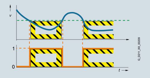
Safe Speed Monitor (SSM)
The SSM function warns when a drive is working below an adjustable speed limit. As long as it remains below the threshold, the function issues a safety-related signal.
Activation
If a speed value drops below a parameterized limit, a safety-related signal is generated. This can, for example, be processed in a safety controller to respond to the event by programming, depending on the situation.
Application
With the SSM function, in the simplest case, a safety door can be unlocked if the speed drops below a non-critical level. Another typical example is that of a centrifuge that may be filled only when it is operating below a configured speed limit.
Customer benefits
Unlike SLS, there is no drive-integrated fault reaction when the speed limit is exceeded. The safe feedback can be evaluated in a safety control unit, allowing the user to respond appropriately to the situation.
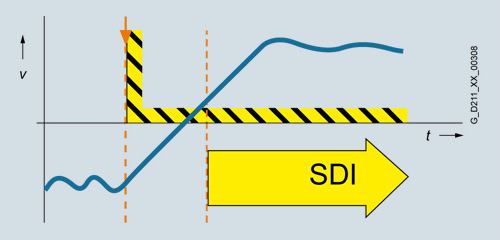
Safe Direction (SDI)
The SDI function ensures that the drive can only move in the selected direction.
Activation
Deviation from the direction of motion currently being monitored is detected reliably and the configured drive-integrated fault reaction is initiated. It is possible to select which direction of rotation is to be monitored.
Application
The SDI function is used when the drive may only move in one direction. A typical application is to permit the operator access to a danger zone, as long as the machine is rotating in the safe direction, i.e. away from the operator. In this state, the operator can feed material into the work zone / remove material from the work zone without danger.
Customer benefits
The function saves the use of external components such as speed monitors and the associated wiring. The release of a danger zone while the machine is moving away from the operator increases productivity. Without the SDI function, the machine must be safely stopped during material loading and removal.
Safely Limited Position (SLP)
The SLP function monitors the axis to ensure that it remains within the permissible traversing range.
Activation
When SLP is activated, the traversing range limited by the configured software limit switches is safely monitored. If the permitted traversing range is exited, a customizable fault reaction occurs. It is possible to toggle between two traversing ranges, even when the machine is in operation.
Application
SLP is used for applications in which machine operators have to enter a protection area, e.g. for feeding in and removing material. Safe monitoring of the axis position ensures that the axis cannot move into the protection area released for operators and so place them in danger, for example, on storage and retrieval machines, gantry cranes or machining centers.
Customer benefits
SLP can be used for highly-effective protection area monitoring. The function does away with the use of external components such as hardware limit switches and the associated wiring expense. Due to the short reaction time following a limit overshoot, safety clearances can be reduced.

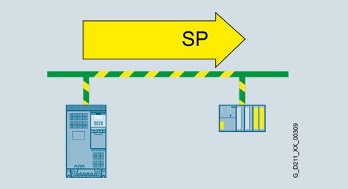
Safe Position (SP)
The SP function transfers the actual position values determined safely in the drive over safe PROFIsafe communication to a safety control.
Activation
In contrast to the SLP function that monitors the current actual position value against a limit and, in the case of an overshoot, activates a drive-integrated fault reaction, SP transfers the current actual position values to the safety control. Position monitoring is implemented in the safety program of the control. Extended PROFIsafe telegrams are available for transferring the position values. The position values can be transferred in 16‑bit or 32‑bit resolution, as required. A time stamp is also transferred with the position values.
Application
Tailor-made safety concepts can be created using the SP function. It is ideal for use on machines that require flexible safety functions. It is extremely versatile and can be used, for example, to implement safe, axis-specific range detection by means of the Safe Cams (SCA) function. The SP function can also be used to implement multi-axis safety concepts, multi-dimensional protection areas and zone concepts.
Customer benefits
Position monitoring or speed monitoring is implemented in the safety program of the control, so the user has the flexibility for implementing tailor-made safety functions. The reaction to a limit overshoot must also be specified in the safety program. This means a higher initial programming outlay, but it does offer the opportunity for initiating different fault reactions.
Basic Functions and Extended Functions
The Safety Integrated functions of the SINAMICS drive system are grouped into Basic Functions and Extended Functions.
- Basic Functions
- Safe Torque Off (STO)
- Safe Brake Control (SBC)
- Safe Stop 1 (SS1)
- Extended Functions
- Safe Stop 1 (SS1) with SBR or SAM
- Safe Stop 2 (SS2) with SAM
- Safe Operating Stop (SOS)
- Safely Limited Speed (SLS)
- Safe Speed Monitor (SSM)
- Safe Direction (SDI)
- Safely Limited Position (SLP)
- Safe Position (SP)
- Safe Brake Test (SBT)
For the Extended Functions Safe Stop 1 (SS1) and Safe Stop 2 (SS2) with SAM, safe acceleration monitoring (SAM) is performed during braking to identify any faults already during the braking phase.
If Safe Stop 1 is used as an encoderless function, a Safe Brake Ramp (SBR) can be configured as an alternative.
The Basic Functions – activated via on-board terminals on the device or via PROFIsafe – do not require an encoder.
Activation of the integrated safety functions
The safety functions for SINAMICS drives can be activated via terminals, e.g. for use of a conventional safety circuit.
For standalone safety solutions for small to medium sized applications, it is frequently sufficient that the various sensing components are directly hardwired to the drive.
For integrated safety solutions, the safety-relevant sequences are generally processed and coordinated in the fail-safe SIMATIC controller. Here, the system components communicate via the PROFINET or PROFIBUS fieldbus. The safety functions are controlled via the safe PROFIsafe communication protocol.
SINAMICS drives can be easily integrated into the plant or system topology.
PROFIsafe
SINAMICS drives support the PROFIsafe profile based on PROFIBUS as well as on PROFINET.
PROFIsafe is an open communications standard that supports standard and safety-related communication over the same communication path (wired or wireless). A second, separate bus system is therefore not necessary. The telegrams that are sent are continually monitored to ensure safety-relevant communication.
Possible errors such as telegrams that have been lost, repeated or received in the incorrect sequence are avoided. This is done by consecutively numbering the telegrams in a safety-relevant fashion, monitoring their reception within a defined time and transferring an ID for transmitter and receiver of a telegram. A CRC (cyclic redundancy check) data security mechanism is also used.
The operating principle of Safety Integrated
Two independent switch-off signal paths
Two independent switch-off signal paths are available. All switch-off signal paths are low active. This ensures that the system is always switched to a safe state if a component fails or in the event of cable breakage. If an error is discovered in the switch-off signal paths, the Safe Torque Off or Safe Stop 1 function is activated (depending on the parameterization) and a system restart inhibited.
Two-channel monitoring structure
All the main hardware and software functions for Safety Integrated are implemented in two independent monitoring channels (e.g. switch-off signal paths, data management, data comparison). A cyclic crosswise comparison of the safety-relevant data in the two monitoring channels is carried out.
The monitoring functions in each monitoring channel work on the principle that a defined state must prevail before each action is carried out and a specific acknowledgement must be made after each action. If these expectations of a monitoring channel are not fulfilled, the drive coasts to a standstill (two channel) and an appropriate message is output.
Forced dormant error detection using test stop
The functions and switch-off signal paths must be tested at least once within a defined time in order to meet requirements as per EN ISO 13849‑1 and IEC 61508 in terms of timely fault detection. This must be implemented either in cyclic manual mode or the test stop must be automatically initiated as part of the process. The test stop cycle is monitored, and after a specific time has been exceeded, an alarm is output. A test stop does not require a POWER ON. The acknowledgment is set by canceling the test stop request.
Examples of when forced dormant error detection must be performed:
- When the drives are at a standstill after the system has been switched on
- Before the protective door is opened
- At defined intervals (e.g. every 8 hours)
- In automatic mode, time and event-driven
Safe actual value sensing with or without encoders
A drive monitor with encoder is necessary for operation of a series of safety functions.
For applications with encoderless mode or with encoders that have no safety capability, the safety functions can also be implemented without encoder. It is not possible to use all safety functions in this case.
The encoderless safety functions can be implemented on request for chassis format units.
In operation without encoder, the actual speed values are calculated from the measured electrical actual values. Therefore, speed monitoring is also possible during operation without encoder.
An encoder that is used for the purposes of motor control has no significance for the safety function here.
Safety Integrated Extended Functions "without encoder" must not be used if the motor, after it has been switched off, can still be accelerated by the mechanical elements of the connected machine component.
In the hoisting gear of a crane, for example, the suspended load can accelerate the motor as soon as the motor is switched off. In this case, the safety functions "without encoder" are not permitted.
A horizontal conveyor, on the other hand, is always braked to a standstill due to friction as soon as the motor is switched off. In this case, the safety functions "without encoder" can be used without any restriction.
The Safety Integrated Function Manual contains additional information about the encoderless safety functions.
http://support.automation.siemens.com/WW/view/en/27103700/133300
The safety functions are listed below with criteria for actual value sensing
Functions | Abbreviation | With encoder | Without encoder | Description | |
|---|---|---|---|---|---|
Basic Functions | Safe Torque Off | STO | Yes | Yes | Safe Torque Off |
Safe Stop 1 | SS1 | Yes | Yes | Safe Stop according to stop category 1 | |
Safe Brake Control | SBC | Yes | Yes | Safe Brake Control | |
Extended Functions | Safe Torque Off | STO | Yes | Yes 1) | Safe Torque Off |
Safe Stop 1 | SS1 | Yes | Yes 1) | Safe Stop according to stop category 1 | |
Safe Brake Control | SBC | Yes | Yes 1) | Safe Brake Control | |
Safe Operating Stop | SOS | Yes | No | Safe monitoring of the standstill position | |
Safe Stop 2 | SS2 | Yes | No | Safe Stop according to stop category 2 | |
Safely Limited Speed | SLS | Yes | Yes 1) | Safe monitoring of the maximum speed | |
Safe Speed Monitor | SSM | Yes | Yes 1) | Safe monitoring of the minimum speed | |
Safe Direction | SDI | Yes | Yes 1) | Safe monitoring of the direction of motion | |
Safely Limited Position | SLP | Yes | No | Safely-limited position | |
Safe Position | SP | Yes | Yes | Safe transfer of position values | |
Safe Brake Test | SBT | Yes | No | Safe test of the required holding torque of a brake |
1) The use of this safety function without encoder is permitted only on request and only for induction motors or synchronous motors of the SIEMOSYN series.
Safe speed/position sensing with encoder
Incremental encoders or absolute encoders with photoelectric sampling are permitted for safe sensing of the position values on a drive. HTL/TTL incremental encoders may also be used.
Safe actual value sensing relies on redundant evaluation of the incremental tracks A/B that supply sin/cos signals of 1 Vpp. Only encoders of the type whose A/B track signals are created and processed using purely analog techniques can be used. The encoder signals are input via the SMC20 Sensor Module Cabinet-Mounted.
For HTL/TTL incremental encoders, safe actual value sensing is achieved by using two independent encoders. The minimum possible speed resolution must also be taken into account. The encoder signals are input via the SMC30 Sensor Module Cabinet-Mounted.
When motors with a DRIVECLiQ interface are used, the speed/position actual values are generated directly in the motor as safe values and transferred to the Control Unit over a safe DRIVECLiQ communication link.
The following can be used for safe speed/position sensing:
- Single-encoder systems or
- 2-encoder systems
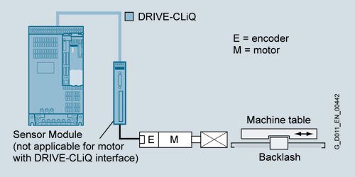
Example: Single-encoder system
In a single-encoder system, the motor encoder is used exclusively for safe actual value sensing. An incremental encoder or absolute encoder with photoelectric sampling must be used in this case.

Example: Dual-encoder system
In the case of the 2-encoder system, the safe actual values for a drive are provided by two separate encoders. The actual values are transferred to the Control Unit over DRIVE-CLiQ. When motors without a DRIVE-CLiQ connection are used, a Sensor Module (SMC20/30, SME20/25/120/125) must be provided. Each measuring system requires a separate DRIVE-CLiQ connection.
For this configuration, either two HTL/TTL encoders, one dual-HTL/TTL encoder or one HTL/TTL encoder and one sin/cos encoder can be used.


 Ответ от производителя может занять до 5 дней и более.

