Standard options Siemens
Опции
B48
Test sequence schedule
Option B48 provides an order-specific test sequence schedule. This will be sent by e-mail approximately 6 weeks following receipt of order in PDF format (English/German).
B38
Spare parts price list
With option B38, a spare parts price list will be supplied for the converter. This list contains the recommended spare parts for commissioning, as well as for 5-year operation.
B43 and B45
Production flowchart
Inadmissible option combinations B43 and B45
Documentation, production flowcharts | B43 | B45 | |
|---|---|---|---|
Generated once | B43 | – | |
Updated every month | B45 | – |
– | Options mutually exclude each other. |
Options B43 and B45 provide production flowcharts. These will be sent by e-mail following receipt of order either in MPP format (Microsoft Project) or in PDF format (English/German) as required. Please select format.
Option | Description |
|---|---|
B43 | Production flowchart: Generated once |
B45 | Production flowchart: Updated every month |
C36, C38, C43, C48 and Y36
External auxiliary power supply
With options C36, C38, C43, C48 and Y36, a connection terminal is available to the customer that can be used to supply loads (cabinet fan, cabinet heater, cabinet lighting, PLC, etc.) from an external power source. The supply system type for options C36, C38, C43, and C48 is grounded (TN/TT system). Only one phase is protected using a suitable miniature circuit breaker. Different voltages and supply system types are defined using option Y36. Please specify additional protection or connection of the N conductor (prescribed in certain countries).
Auxiliary DC voltage on request.
Option | Description |
|---|---|
C36 | Connection of 230 V 1 AC 50 Hz auxiliary voltage provided by the customer |
C38 | Connection of 400 V 3 AC 50 Hz auxiliary voltage provided by the customer |
C43 | Connection of 500 V 3 AC 50 Hz auxiliary voltage provided by the customer |
C48 | Connection of 690 V 3 AC 50 Hz auxiliary voltage provided by the customer |
Y36 | Connection of different level of 3-phase AC voltage provided by the customer; please specify voltage |
C56, C57 and Y55
External control voltage supply
Inadmissible option combinations C56, C57 and Y55
External control voltage supply | C56 | C57 | Y55 | |
|---|---|---|---|---|
Connection of 230 V 1 AC 50 Hz control voltage provided by the customer, no UPS backup | C56 | – | – | |
Connection of 230 V 1 AC 50 Hz control voltage provided by the customer; UPS backup | C57 | – | – | |
Connection of different level of single-phase AC voltage provided by the customer; please specify voltage | Y55 | – | – |
– | Options mutually exclude each other. |
With options C56, C57 and Y55, an external current source is defined for the converter. This is necessary in the following situations:
- If the display should indicate correctly even though no line voltage is present and the converter should not indicate a fault.
- The initialization time for the converter of approximately 3 s for temporary power failures does not apply in the case of an external, backed-up control voltage (precharging and synchronization time, however, remain unaffected).
If no external control voltage supply is selected, the converter will be supplied from the DC link in the case of compact units without a main contactor. For the following compact units, an additional board is required for mains supply backup (option E85):
Type | Converter type |
6SE0100‑1A❑23‑4❑A7 | 2T2A‑07600‑030 |
6SE0100‑1A❑24‑2❑A7 | 2T2A‑07600-037 |
6SE0100‑1A❑25‑0❑A7 | 2T2A‑07600-045 |
6SE0100‑1A❑25‑8❑A7 | 2T2A‑07600-055 |
6SE0100‑1A❑28‑0❑A7 | 2T2A‑07600‑075 |
6SE0100‑1A❑31‑0❑A7 | 2T2A‑07600‑090 |
6SE0100‑1A❑31‑2❑A7 | 2T2A‑07600‑110 |
6SE0100‑1A❑31‑4❑A7 | 2T2A‑07600‑132 |
6SE0100‑1A❑31‑7❑A7 | 2T2A‑07600‑160 |
6SE0100‑1A❑32‑1❑A7 | 2T2A‑07600‑200 |
For cabinet units with and without input contactors and for cabinet systems with input contactors, the control voltage is generated from the converter line voltage by a control transformer.
Advantage:
When the converter control voltage is supplied from the DC link, this provides a backup function for drives with a coupled rotating mass (e.g. fan drive). This means that the DC link of the converter is maintained for a short time in the case of a temporary voltage drop or power failure due to continued rotation of the rotating mass on the motor. The control voltage for the converter is backed-up until the DC link voltage fails due to standstill of the rotating mass, or until the parameter "t-restart" causes switch-off.
Option | Description |
|---|---|
C56 | Connection for 230 V 1 AC 50 Hz external control voltage provided by the customer, no UPS backup |
C57 | Connection for 230 V 1 AC 50 Hz external control voltage provided by the customer, with UPS backup |
Y55 | Connection for different level of single-phase AC control voltage with 47 to 63 Hz provided by the customer, please specify voltage |
D01, D02, D04, D05 and D06
Converter documentation
For the scope of the converter documentation, see the "Documentation" section under "Services and documentation". A CD comprising a manual and IMS is supplied with every converter.
Option | Description |
|---|---|
D01 | Manual and set of diagrams in PDF format per e-mail, German/English |
D02 | Manual in PDF format, set of diagrams in DXF format per e-mail, German/English |
D04 | Manual and set of diagrams, single hardcopy, German/English |
D05 | Manual and set of diagrams in PDF format on CD, German/English |
D06 | Manual in PDF format, set of diagrams in DWG format on CD, German/English |
Note:
Please ask your Siemens sales partner if the documentation or set of diagrams are required in a different language.
G13, G14, G15, G16 and G18
Accessories for IMS (Inverter Management Software)
G13 USB PROFIBUS interface (supplied separately packed)

G13 Softing PROFIBUS (PROFIBUS interface)
Active single-channel USB high-speed interface for connecting a PC with IMS to a PROFIBUS network. The interface is suitable for control and visualization tasks as well as for parameterization and analysis applications via the IMS. All SINAMICS G180 converters in the PROFIBUS network can be addressed.
No additional power connection is required for this converter. The cable on the converter has a double PROFIBUS SUB-D 9-pin connection (socket/plug with end wiring) for connecting to PROFIBUS. As a result, a simple connection is possible directly on the SINAMICS G180 with PROFIBUS board (G01).
Note:
The installation notes in the help function of IMS must be observed.
G14 Ethernet-PROFIBUS gateway
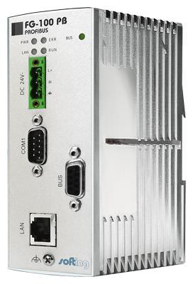
G14 Softing FG-100PB
Gateway between host systems on Ethernet and the PROFIBUS bus system. Suitable for network configuration, device parameterization or acquisition of operating data. All SINAMICS G180 converters in the PROFIBUS system can be monitored and parameterized.
The Ethernet-PROFIBUS gateway can be installed in the converter cabinet or supplied separately packed. Please specify your requirements in the order. The gateway is normally installed at the most favorable transition point between Ethernet and PROFIBUS.
Technical data:
- Dimensions (W × H × D) 47 × 131 × 11 mm
- Mounting on 35 mm DIN rail
- Power supply 24 V DC (±20 %); 0.3 A
- Operating temperature 0 °C to 55 °C
Scope of supply:
- Ethernet interface on PROFIBUS
- Installation manual
- CD with Windows drivers
Note:
The installation notes in the help function of IMS must be observed.
If the Ethernet-PROFIBUS gateway is supplied separately with the converter, a separately power supply unit is required. This is not part of the scope of supply.
G15 Ethernet to RS232/485/422 converter (supplied separately packed)
With option G15 a serial/Ethernet converter is supplied separately packed. If several converters are interconnected over an RS485 network, up to 128 converters can be connected to Ethernet using one converter.
Technical data:
- Dimensions (W × H × D) 151 × 75 × 26 mm
- Power supply 10 to 30 V DC; 1.6 W
Note:
The installation notes in the help function of IMS must be observed.
An external power supply unit is required for the Ethernet to RS232/485/422 converter which is not part of the scope of supply.
G16 USB cable A/B, 2 m (supplied separately packed)

G16 USB cable A/B (example shown)
Option G16 comprises a 2 m long USB cable for parameterizing the SINAMICS G180 from the IMS.
G18 USB connector on front of control cabinet door

G18 USB connector on front of control cabinet door (example shown)
With option G18 a USB connector is installed in the control cabinet door that allows the converter to be parameterized from the IMS without having to open the cabinet door. IP65 degree of protection.
M96, M93 and M94
Marking of cable cores and items of equipment
Inadmissible option combinations M93 and M94
Marking of cable cores and | M96 | M93 | M94 | |
|---|---|---|---|---|
Dual marking of items of equipment | M96 | ✓ | ✓ | |
Cable marking, C-type | M93 | ✓ | – | |
Cable marking (shrink-on sleeve) | M94 | ✓ | – |
✓ | Options are combinable. |
– | Options mutually exclude each other. |
M96 Dual marking of items of equipment
M96 Example of dual marking of items of equipment
With option M96 the items of equipment are marked twice, once on the equipment and once directly adjacent to the mounting location of the equipment.
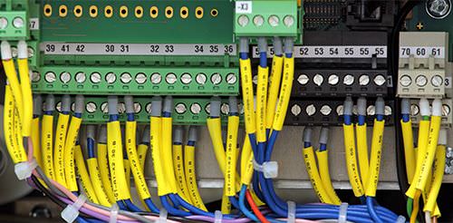
M93 Cable marking, C-type
M93 Example of cable marking, C-type
- Cable markings in the shape of the letter C are clipped onto the control cables.
- Larger power cables are labeled using shrink-on sleeves.
- The terminal designation only is numbered on the cable and not the item designation.
Example:
Terminal –X2:41 → Cable is marked with 41.
M94 Cable marking (shrink-on sleeve)
M94 Example of cable marking
- Cable markings using shrink-on sleeves are attached to the cables.
- The terminal designation and the item designation are labeled on the cable.
Example:
Terminal –X2:41 → Cable is marked with –X2:41.
E85
Board for mains supply backup
To enable the control voltage to be generated from the DC link for the following converter types, option E85 (series-connected power supply unit for mains supply backup) is required.
This option must be ordered separately for all cabinet units and for the following compact units:
Type | Converter type |
|---|---|
6SE0100‑1A❑23‑4❑A7 | 2T2A‑07600‑030 |
6SE0100‑1A❑24‑2❑A7 | 2T2A‑07600‑037 |
6SE0100‑1A❑25‑0❑A7 | 2T2A‑07600‑045 |
6SE0100‑1A❑25‑8❑A7 | 2T2A‑07600‑055 |
6SE0100‑1A❑28‑0❑A7 | 2T2A‑07600‑075 |
6SE0100‑1A❑31‑0❑A7 | 2T2A‑07600‑090 |
6SE0100‑1A❑31‑2❑A7 | 2T2A‑07600‑110 |
6SE0100‑1A❑31‑4❑A7 | 2T2A‑07600‑132 |
6SE0100‑1A❑31‑7❑A7 | 2T2A‑07600‑160 |
6SE0100‑1A❑32‑1❑A7 | 2T2A‑07600‑200 |
Advantage:
When the converter control voltage is supplied from the DC link, this provides a backup function for drives with a coupled rotating mass (e.g. fan drive). This means that the DC link of the converter is maintained for a short time in the case of a temporary voltage drop or power failure due to continued rotation of the rotating mass on the motor. The control voltage for the converter is therefore backed up for a short time.
G01, G12, G20, G22 and G27
Additional boards for bus connection
Inadmissible option combinations G01, G20, G22, G27
Additional boards for bus connection | G01 | G12 | G20 | G22 | G27 | |
|---|---|---|---|---|---|---|
Board for PROFIBUS DPV1 | G01 | ✓ | – | – | – | |
PROFIBUS expansion module for option G10 or G11 | G12 | ✓ | ✓ | ✓ | ✓ | |
Board for CANopen | G20 | – | ✓ | – | – | |
Board for Modbus RTU | G22 | – | ✓ | – | – | |
Board for Modbus TCP | G27 | – | ✓ | – | – |
✓ | Options are combinable. |
– | Options mutually exclude each other. |
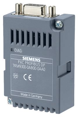
G01 Board for PROFIBUS DPV1

G01 PROFIBUS board for SINAMICS G180 in compact unit

G01 PROFIBUS board for SINAMICS G180 in cabinet unit
Option G01 for the PROFIBUS DPV1 board is suitable for cyclic and non-cyclic data transfer and can be retrofitted in compact units and cabinet units at any time.
G12 PROFIBUS expansion module for option G10 or G11 (SENTRON PAC3200 power monitoring device)
G12 PROFIBUS expansion module
Option G12 allows the SENTRON PAC3200 power monitoring device to be connected to PROFIBUS. This expansion module can only be ordered in conjunction with option G10 or G11.
G20 Board for CANopen

G20 CANopen
Option G20 (board for CANopen) transfers data in binary form. Fieldbus connection is implemented in accordance with the CANopen standard. This board can be retrofitted in compact units and cabinet units at any time, provided that no other bus system has been installed beforehand.
G22 Board for Modbus RTU
G22 Modbus RTU
Option G22 (board for Modbus RTU) transfers data in binary form. This board can be retrofitted in compact units and cabinet units at any time, provided that no other bus system has been installed beforehand.
G27 Board for Modbus TCP

G27 Modbus TCP
Option G27 (board for Modbus TCP) is very similar to Option G22 (board for Modbus RTU), except that TCP packages are used to send the data. This board can be retrofitted in compact units and cabinet units at any time, provided that no other bus system has been installed beforehand.
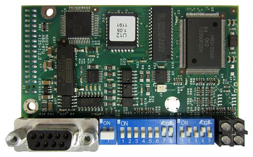
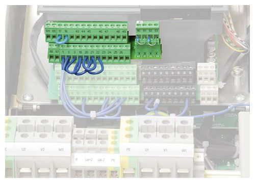
G02, G03, G04 and G05
Peripheral boards 1 to 4
Inadmissible option combinations G02, G03, G04 and G05
Peripheral board 1 … 4 | G02 | G03 | G04 | G05 | |
|---|---|---|---|---|---|
Peripheral board 1 | G02 | – | – | – | |
Peripheral board 2 | G03 | – | – | – | |
Peripheral board 3 | G04 | – | – | – | |
Peripheral board 4 | G05 | – | – | – |
– | Options mutually exclude each other. |
The functionality of the converter is expanded with the peripheral board. Every converter can be fitted or even retrofitted with one of these peripheral boards.
Boards with safety-related inputs (PTC thermistor or the function "Safe Torque Off") are only permitted to be retrofitted by our authorized qualified personnel.
In addition to the main board, peripheral boards 2 and 4 are also expanded by a daughterboard which contains the circuitry for the PTC thermistor inputs.
Peripheral board | ||||
|---|---|---|---|---|
1 | 2 | 3 | 4 | |
2 PTC thermistor inputs for ATEX-certified motor temperature monitoring for motors in hazardous zones (prewarning/trip) | ● | ● | ||
One input "Safe Torque Off" acc. to EN ISO 13849‑1, Cat. 3. PL d or SIL 2 acc. to EN 61508 | ● | ● | ||
9 digital inputs (DI) | ● | ● | ||
3 relay outputs (DO) | ● | ● | ||
2 analog outputs (AO) | ● | ● | ● | ● |
24 V / 300 mA power supply unit | ● | ● | ||
G02 Peripheral board 1

G02 Peripheral board 1
Option G02 (peripheral board 1) provides in addition to standard converter terminals:
- 2 analog outputs (AO) 4 to 20 mA/0 to 10 V
Standard assignment of inputs/outputs
The table below provides an overview of the pre-assignment function of interfaces in the pin assignments for the "Standard" application.
Signal designation | Function |
|---|---|
Internal PTC thermistor input 90, 91, 92, 93 | Not assigned |
Internal analog output 64, 65 | Torque |
Internal analog output 66, 67 | Power |

G02 Circuit diagram for peripheral board 1
G03 Peripheral board 2
G03 Peripheral board 2 in the compact unit
Option G03 (peripheral board 2) provides in addition to standard converter terminals:
- 2 analog outputs (AO) 4 to 20 mA/0 to 10 V
- 2 PTC thermistor inputs for ATEX-certified motor temperature monitoring for motors in hazardous zones (prewarning/trip)
- PTC thermistor monitoring without contactor through monitoring unit integrated in converter, certified to SIL 1 in accordance with EN 61508
The converter controller processes the signal of the peripheral board. In the event of excessive motor temperature, or the function "Safe Torque Off", the converter inhibits the firing signals of the IGBTs. The voltage supply of the driver stages is also switched off. These two redundant, diverse and self-monitored switch-off paths ensure that the power infeed to the motor is safely interrupted. Further heating or rotation of the motor is excluded. The converter can only be reset or switched on when the motor has cooled down sufficiently and the fault has been acknowledged. When the voltage fails, the converter safely interrupts the power infeed to the motor, because firing signals are no longer transferred. If a fault was active at the moment of power failure, the converter will also be in fault status when power is restored.
Standard assignment of inputs/outputs
The table below provides an overview of the pre-assignment function of interfaces in the pin assignments for the "Standard" application.
Signal designation | Function |
|---|---|
Internal PTC thermistor input 90, 91 | PTC thermistor for disconnection (ATEX-certified) |
Internal PTC thermistor input 92, 93 | PTC thermistor for warning |
Internal analog output 64, 65 | Torque |
Internal analog output 66, 67 | Power |

G03 Circuit diagram for peripheral board 2
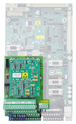
G04 Peripheral board 3
G04 Peripheral board 3 in the compact unit
Option G04 (peripheral board 3) provides in addition to standard converter terminals:
- 2 analog outputs (AO) 4 to 20 mA/0 to 10 V
- One digital input "Safe Torque Off" (STO, single-channel or two-channel) acc. to EN ISO 13849‑1, Cat. 3 or SIL 2 acc. to EN 61508
9 digital inputs (DI) - 3 relay outputs (DO)
In addition, the relay outputs here are not only isolated from the converter electronics but also from each other. - 24 V / 300 mA power supply unit
SIL 2 (acc. to EN 61508) – STO (Safe Torque Off).
Safe Torque Off (STO) function implemented according to SIL 2 to EN 61508.
The "Safe Torque Off" (STO) function has a redundant switch-off path in the converter. The implementation is performed using hardware. A relay in the power unit of the converter disconnects the power supply of the IGBT driver. A second circuit, also via hardware, produces a controller disable.
The "Safe Torque Off" input can be implemented with either one or two channels. The board is coded for single-channel activation at the factory. If two-channel activation is required, please specify this in the order. Digital input X2:24 is reserved for the two-channel version.
Standard assignment of inputs/outputs
The table below provides an overview of the pre-assignment function of interfaces in the pin assignments for the "Standard" application.
Signal designation | Function |
|---|---|
Internal digital input 19, 20 | 24 V DC; "Safe Torque Off" acc. to EN ISO 13849‑1, Cat. 3; or SIL 2 acc. to EN 61508 |
Internal digital input 6, 7, 21, 22, 23, 24, 25, 26 | Freely parameterizable |
Internal PTC thermistor input 90, 91, 92, 93 | Not assigned |
Internal digital output 43, 44, 45 | Relay 5: "Motor temperature trip" |
Internal digital output 46, 47 | Relay 6: "Automatic mode (normal)" |
Internal digital output 48, 49 | Relay 7: "Speed 0" |
Internal analog output 64, 65 | Torque |
Internal analog output 66, 67 | Power |
NAMUR-compliant assignment of inputs/outputs
The table below provides an overview of the pre-assignment function of interfaces in the pin assignments for the "NAMUR" application.
Signal designation | Function |
|---|---|
Internal digital input 17, 18 | Forced power supply disconnection |
Internal digital input 19, 20 | +24 V DC; forced inverter inhibit |
Internal digital input 6 | Rapid stop global 1 |
Internal digital input 7 | Separately driven fan of motor activated |
Internal digital input 21 | External fault |
Internal digital input 22 | External warning |
Internal digital input 23 | Operation, bus |
Internal digital input 24 | Controller ON |
Internal digital input 25 | Fixed setpoint 1 |
Internal digital input 26 | Fixed setpoint 2 |
Internal PTC thermistor input 90, 91, 92, 93 | Not assigned |
Internal digital output 43, 44, 45 | Relay 5: "Motor temperature trip" |
Internal digital output 46, 47 | Relay 6: "Automatic mode (normal)" |
Internal digital output 48, 49 | Relay 7: "Speed 0" |
Internal analog output 64, 65 | Torque |
Internal analog output 66, 67 | Power |

G04 Circuit diagram for peripheral board 3
G05 Peripheral board 4
G05 Peripheral board 4 in the compact unit
G05 Peripheral board 4 in the cabinet unit
Option G05 (peripheral board 4) provides in addition to the standard terminals:
- 2 analog outputs (AO) 4 to 20 mA/0 to 10 V
- 2 PTC thermistor inputs, one certified for ATEX (disconnection), one warning for motor temperature monitoring of motors in a hazardous area
- One digital input "Safe Torque Off" acc. to EN ISO 13849‑1, Cat. 3/(STO) implemented according to SIL 2 acc. to EN 61508
9 digital inputs (DI) - 3 relay outputs (DO)
In addition, the relay outputs here are not only isolated from the converter electronics but also from each other. - 24 V / 300 mA power supply unit
- ATEX-certified PTC thermistor monitoring without contactor through monitoring unit integrated in converter, certified to SIL 1 in accordance with EN 61508
PTC thermistor monitoring without contactor through monitoring unit integrated in converter, certified to SIL 1 in accordance with EN 61508 or Category 2, PL c in accordance with EN ISO 13849‑1
The converter controller processes the signal of the peripheral board. In the event of excessive motor temperature, or the function "Safe Torque Off", the converter inhibits the firing signals of the IGBTs. The voltage supply of the driver stages is also switched off. These two switch-off paths ensure that the power infeed to the motor is immediately interrupted. Further heating or rotation of the motor is excluded. The converter can only be reset or switched on when the motor has cooled down sufficiently. When the voltage fails, the converter safely interrupts the power infeed to the motor, because firing signals are no longer transferred. If a fault was active at the moment of power failure, the converter will also be in fault status when power is restored.
SIL 2 (acc. to EN 61508) – STO (Safe Torque Off).
Safe Torque Off (STO) function implemented according to SIL 2 to EN 61508.
The "Safe Torque Off" (STO) function has a redundant switch-off path in the converter. The implementation is performed using hardware. A relay in the power unit of the converter disconnects the power supply of the IGBT driver. A second circuit, also via hardware, produces a controller disable. Both switch-off paths are based on the closed-circuit principle, i.e. a failure of the control voltage results in shutdown of the converter.
The "Safe Torque Off" input can be implemented with either one or two channels. The board is coded for single-channel activation at the factory. If two-channel activation is required, please specify this in the order. Digital input X2:24 is reserved for the two-channel version.
Subsequent changeover from single-channel to two-channel is only permitted to be implemented by our authorized qualified personnel.
Standard assignment of inputs/outputs
The table below provides an overview of the pre-assignment function of interfaces in the pin assignments for the "Standard" application.
Signal designation | Function |
|---|---|
Internal digital input 19, 20 | 24 V DC; "Safe Torque Off" acc. to EN ISO 13849‑1, Cat. 3; or SIL 2 acc. to EN 61508 |
Internal digital input 6, 7, 21, 22, 23, 24, 25, 26 | Freely parameterizable |
Internal PTC thermistor input 90, 91 | PTC thermistor for disconnection (ATEX-certified) |
Internal PTC thermistor input 92, 93 | PTC thermistor for warning |
Internal digital output 43, 44, 45 | Relay 5: "Motor temperature trip" |
Internal digital output 46, 47 | Relay 6: "Automatic mode (normal)" |
Internal digital output 48, 49 | Relay 7: "Speed 0" |
Internal analog output 64, 65 | Torque |
Internal analog output 66, 67 | Power |
NAMUR-compliant assignment of inputs/outputs
The table below provides an overview of the pre-assignment function of interfaces in the pin assignments for the "NAMUR" application.
Signal designation | Function |
|---|---|
Internal digital input 17, 18 | Forced power supply disconnection |
Internal digital input 19, 20 | +24 V DC; forced inverter inhibit |
Internal digital input 6 | Rapid stop global 1 |
Internal digital input 7 | Separately driven fan of motor activated |
Internal digital input 21 | External fault |
Internal digital input 22 | External warning |
Internal digital input 23 | Operation, bus |
Internal digital input 24 | Controller ON |
Internal digital input 25 | Fixed setpoint 1 |
Internal digital input 26 | Fixed setpoint 2 |
Internal PTC thermistor input 90, 91 | PTC thermistor for disconnection (ATEX-certified) |
Internal PTC thermistor input 92, 93 | PTC thermistor for warning |
Internal digital output 43, 44, 45 | Relay 5: "Motor temperature trip" |
Internal digital output 46, 47 | Relay 6: "Automatic mode (normal)" |
Internal digital output 48, 49 | Relay 7: "Speed 0" |
Internal analog output 64, 65 | Torque |
Internal analog output 66, 67 | Power |

G05 Circuit diagram for peripheral board 4
G10, G11, K14, K15 and K37
Control elements and display instruments in control cabinet door
Inadmissible option combinations G10 and G11
Control elements and display instruments in cabinet door | G10 | G11 | K14 | K15 | K37 | |
|---|---|---|---|---|---|---|
SENTRON PAC3200 power monitoring device (without current transformer) | G10 | – | ✓ | ✓ | ✓ | |
SENTRON PAC3200 power monitoring device (with current transformer) | G11 | – | ✓ | ✓ | ✓ | |
External Запрос коммерческого предложения× Сообщение отправлено× В ближайшее время сообщение будет обработано. Письмо с номером обращения отправлено на Ваш почтовый ящик. Спасибо за то, что выбрали Первый ZIP! Что-то пошло не так...× К сожалению, наша система расценила Ваше сообщение как спам. Если это произошло по ошибке, пожалуйста, обратитесь к нам по электронной почте. Приносим извинения за возможные неудобства.  Вы отправляете нам запрос  Если у нас есть прайс-лист, мы отправляем Вам ответ в течение дня. А если у нас нет прайс-листа по запрошенным товарам?     Если у нас нет прайс-листа, мы отправляем запрос производителю.  Ответ от производителя может занять до 5 дней и более. Ответ от производителя может занять до 5 дней и более.  Запрос производителю мы отправляем только для конечных потребителей.  Торгующим организациям коммерческие предложения предоставляются только по прайсовым позициям: Siemens Beckhoff Pepperl+Fuchs Phoenix Contact PILZ Turck Leuze Electronic Endress+Hauser Murr Elektronik Schmersal |