


Корпуса шкафов управления DOLD
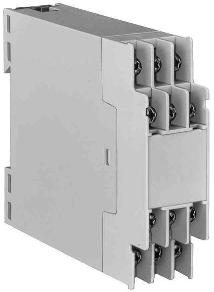
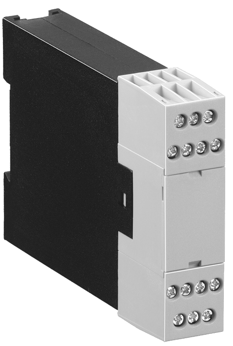
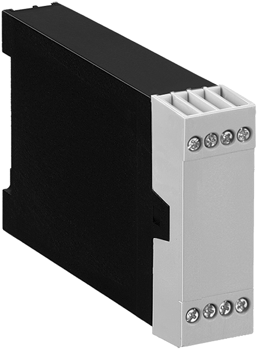
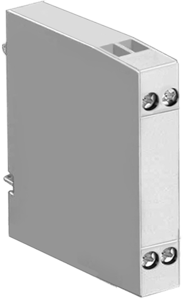
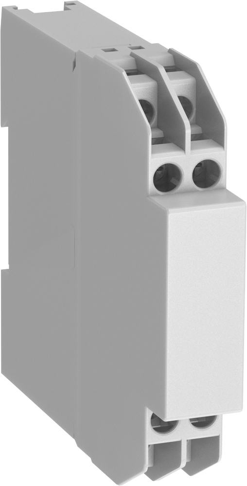
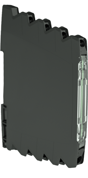
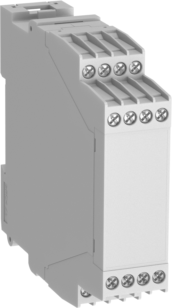

components, indicating and operating
elements
• Hinged front panel (also available with
snap-in marking plate)
• Push-In system for conductors up to
2,5 mm²
• 8 connections, tightly integrated on 4 tiers
• Optionally with InRailBus for a quick and
reliable transmission of data and energy
• Different colours on request
Товар в корзине.
Перейти в корзину
• max. terminals 12 / 18 / 24 / 36 / 48 / 72 / 96
at 2,5 mm2 cross section
• up to 30 terminals on three levels,
per 22.5 mm module width.
• optional in-rail-bus system for quick
and reliable data and energy transfer
Товар в корзине.
Перейти в корзину
• max. terminals 12 / 18 / 24 / 36 / 48 / 72 / 96
at 2,5 mm2 cross section
• up to 30 terminals on three levels,
per 22.5 mm module width.
• optional in-rail-bus system for quick
and reliable data and energy transfer
Товар в корзине.
Перейти в корзину
• max. terminals 12 / 18 / 24 / 36 / 48 / 72 / 96
at 2,5 mm2 cross section
• up to 30 terminals on three levels,
per 22.5 mm module width.
• optional in-rail-bus system for quick
and reliable data and energy transfer
Товар в корзине.
Перейти в корзину
• max. terminals 12 / 18 / 24 / 36 / 48 / 72 / 96
at 2,5 mm2 cross section
• up to 30 terminals on three levels,
per 22.5 mm module width.
• optional in-rail-bus system for quick
and reliable data and energy transfer
Товар в корзине.
Перейти в корзину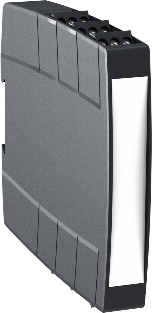
• max. terminals 12 / 18 / 24 / 36 / 48 / 72 / 96
at 2,5 mm2 cross section
• up to 30 terminals on three levels,
per 22.5 mm module width.
• optional in-rail-bus system for quick
and reliable data and energy transfer
Товар в корзине.
Перейти в корзину
• max. terminals 12 / 18 / 24 / 36 / 48 / 72 / 96
at 2,5 mm2 cross section
• up to 30 terminals on three levels,
per 22.5 mm module width.
• optional in-rail-bus system for quick
and reliable data and energy transfer
Товар в корзине.
Перейти в корзину
components, indicating and operating
elements
• Hinged front panel (also available with
snap-in marking plate)
• Screw connection system for conductors
up to 2,5 mm²
• 8 connections, tightly integrated on 4 tiers
• Optionally with InRailBus for a quick and
reliable transmission of data and energy
• Different colours on request
Товар в корзине.
Перейти в корзину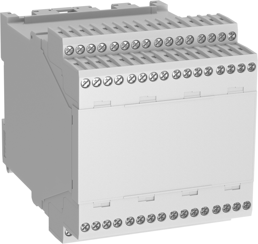
• max. 16 / 32 / 48 / 64 terminals
• Large, variable front plate surface
• Large cross section of connections possible
(e.g. 2 x 1.5 mm2 with stranded ferruled)
• Max. current carrying capacity 16 A
• Machine soldered terminal block,
use of heat-resistant plastic means no
cover for the terminal block facing the
soldering bath is required
• Large plus-minus screws enable high
tightening torques
• High-voltage test complying with IEC 60 439-1
• Printed circuit board density t = 1.5 mm and
1 mm possible
Товар в корзине.
Перейти в корзину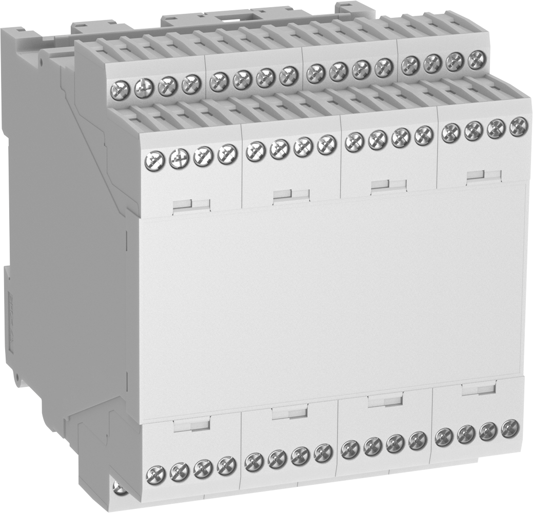
• max. 16 / 32 / 48 / 64 terminals
• Large, variable front plate surface
• Large cross section of connections possible
(e.g. 2 x 1.5 mm2 with stranded ferruled)
• Max. current carrying capacity 16 A
• Machine soldered terminal block,
use of heat-resistant plastic means no
cover for the terminal block facing the
soldering bath is required
• Large plus-minus screws enable high
tightening torques
• High-voltage test complying with IEC 60 439-1
• Printed circuit board density t = 1.5 mm and
1 mm possible
Товар в корзине.
Перейти в корзину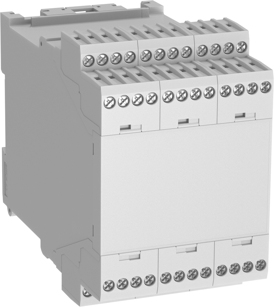
• max. 16 / 32 / 48 / 64 terminals
• Large, variable front plate surface
• Large cross section of connections possible
(e.g. 2 x 1.5 mm2 with stranded ferruled)
• Max. current carrying capacity 16 A
• Machine soldered terminal block,
use of heat-resistant plastic means no
cover for the terminal block facing the
soldering bath is required
• Large plus-minus screws enable high
tightening torques
• High-voltage test complying with IEC 60 439-1
• Printed circuit board density t = 1.5 mm and
1 mm possible
Товар в корзине.
Перейти в корзину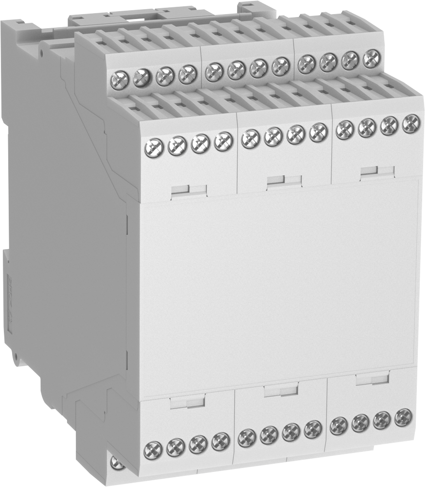
• max. 16 / 32 / 48 / 64 terminals
• Large, variable front plate surface
• Large cross section of connections possible
(e.g. 2 x 1.5 mm2 with stranded ferruled)
• Max. current carrying capacity 16 A
• Machine soldered terminal block,
use of heat-resistant plastic means no
cover for the terminal block facing the
soldering bath is required
• Large plus-minus screws enable high
tightening torques
• High-voltage test complying with IEC 60 439-1
• Printed circuit board density t = 1.5 mm and
1 mm possible
Товар в корзине.
Перейти в корзину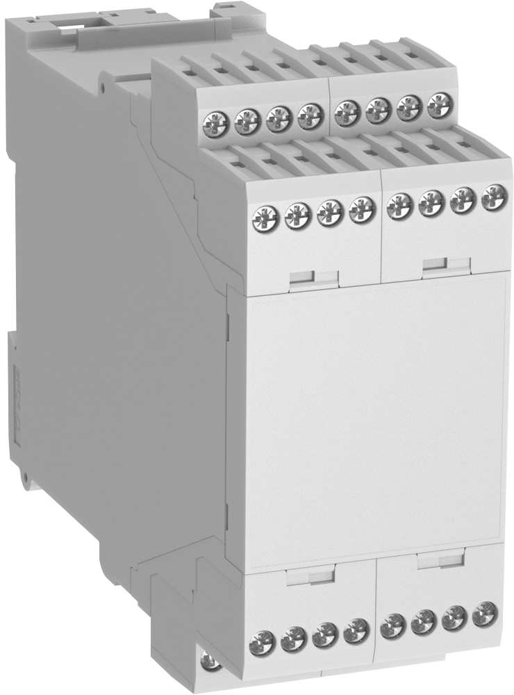
• max. 16 / 32 / 48 / 64 terminals
• Large, variable front plate surface
• Large cross section of connections possible
(e.g. 2 x 1.5 mm2 with stranded ferruled)
• Max. current carrying capacity 16 A
• Machine soldered terminal block,
use of heat-resistant plastic means no
cover for the terminal block facing the
soldering bath is required
• Large plus-minus screws enable high
tightening torques
• High-voltage test complying with IEC 60 439-1
• Printed circuit board density t = 1.5 mm and
1 mm possible
Товар в корзине.
Перейти в корзину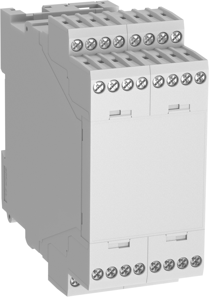
• max. 16 / 32 / 48 / 64 terminals
• Large, variable front plate surface
• Large cross section of connections possible
(e.g. 2 x 1.5 mm2 with stranded ferruled)
• Max. current carrying capacity 16 A
• Machine soldered terminal block,
use of heat-resistant plastic means no
cover for the terminal block facing the
soldering bath is required
• Large plus-minus screws enable high
tightening torques
• High-voltage test complying with IEC 60 439-1
• Printed circuit board density t = 1.5 mm and
1 mm possible
Товар в корзине.
Перейти в корзину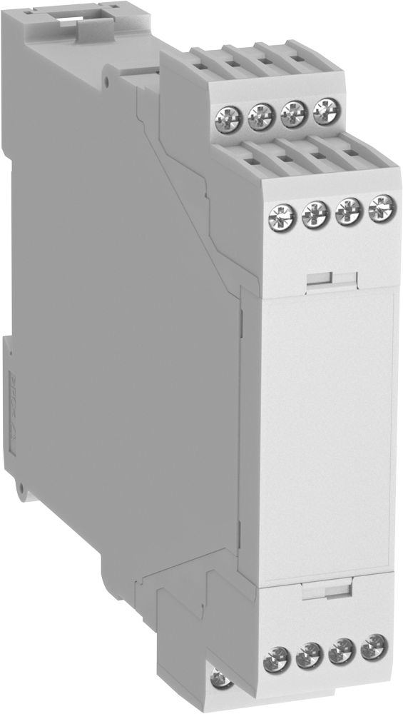
• max. 16 / 32 / 48 / 64 terminals
• Large, variable front plate surface
• Large cross section of connections possible
(e.g. 2 x 1.5 mm2 with stranded ferruled)
• Max. current carrying capacity 16 A
• Machine soldered terminal block,
use of heat-resistant plastic means no
cover for the terminal block facing the
soldering bath is required
• Large plus-minus screws enable high
tightening torques
• High-voltage test complying with IEC 60 439-1
• Printed circuit board density t = 1.5 mm and
1 mm possible
Товар в корзине.
Перейти в корзину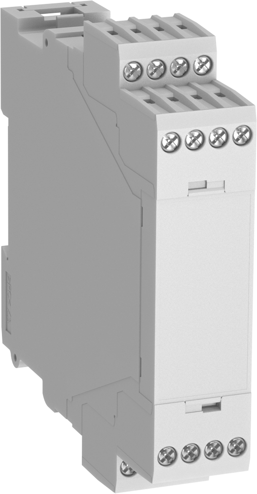
• max. 16 / 32 / 48 / 64 terminals
• Large, variable front plate surface
• Large cross section of connections possible
(e.g. 2 x 1.5 mm2 with stranded ferruled)
• Max. current carrying capacity 16 A
• Machine soldered terminal block,
use of heat-resistant plastic means no
cover for the terminal block facing the
soldering bath is required
• Large plus-minus screws enable high
tightening torques
• High-voltage test complying with IEC 60 439-1
• Printed circuit board density t = 1.5 mm and
1 mm possible
Товар в корзине.
Перейти в корзину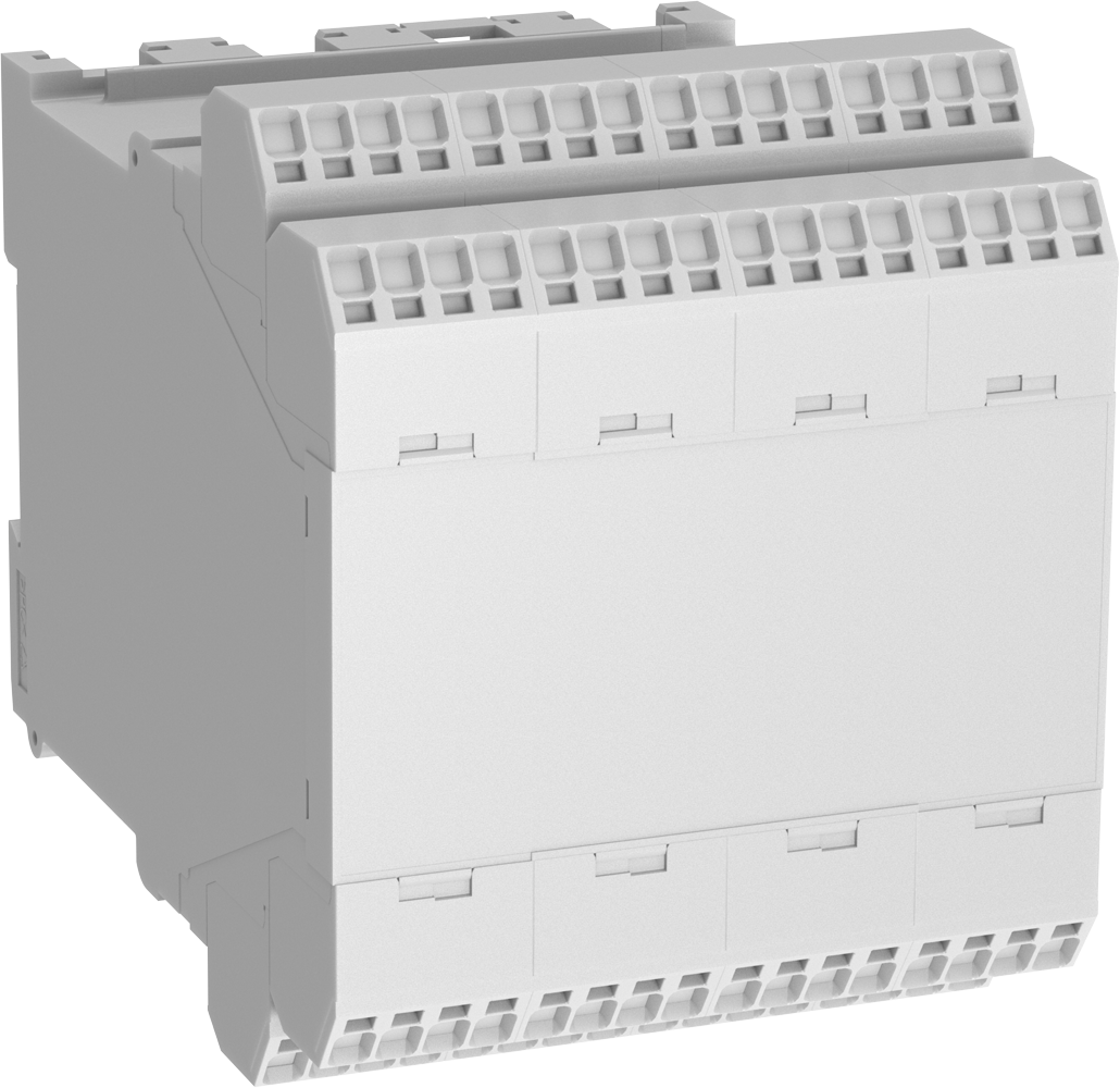
• Max. 16 / 32 / 48 / 64 spring cage clamps
• Large, variable front plate surface
• Max. current carrying capacity 16 A
• Machine soldered terminal block,
use of heat-resistant plastic means no
cover for the terminal block facing the
soldering bath is required
• Easy and quick connecting of conductors:
solid wire and flexible wire with
end ferrule can be inserted directly
(saving of time in comparsion to screw
terminals: 50 - 80 %)
• Easy removing of conductors (put in a
screwdriver according to DIN 5264-A 0.5 x 3)
• High spring force for a secure connection
• Printed circuit board density t = 1.5 mm
and 1 mm possible
Товар в корзине.
Перейти в корзину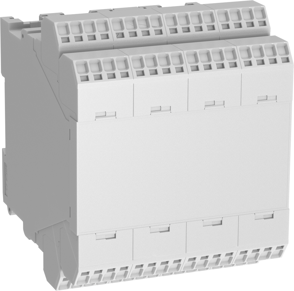
• Max. 16 / 32 / 48 / 64 spring cage clamps
• Large, variable front plate surface
• Max. current carrying capacity 16 A
• Machine soldered terminal block,
use of heat-resistant plastic means no
cover for the terminal block facing the
soldering bath is required
• Easy and quick connecting of conductors:
solid wire and flexible wire with
end ferrule can be inserted directly
(saving of time in comparsion to screw
terminals: 50 - 80 %)
• Easy removing of conductors (put in a
screwdriver according to DIN 5264-A 0.5 x 3)
• High spring force for a secure connection
• Printed circuit board density t = 1.5 mm
and 1 mm possible
Товар в корзине.
Перейти в корзину
• Max. 16 / 32 / 48 / 64 spring cage clamps
• Large, variable front plate surface
• Max. current carrying capacity 16 A
• Machine soldered terminal block,
use of heat-resistant plastic means no
cover for the terminal block facing the
soldering bath is required
• Easy and quick connecting of conductors:
solid wire and flexible wire with
end ferrule can be inserted directly
(saving of time in comparsion to screw
terminals: 50 - 80 %)
• Easy removing of conductors (put in a
screwdriver according to DIN 5264-A 0.5 x 3)
• High spring force for a secure connection
• Printed circuit board density t = 1.5 mm
and 1 mm possible
Товар в корзине.
Перейти в корзину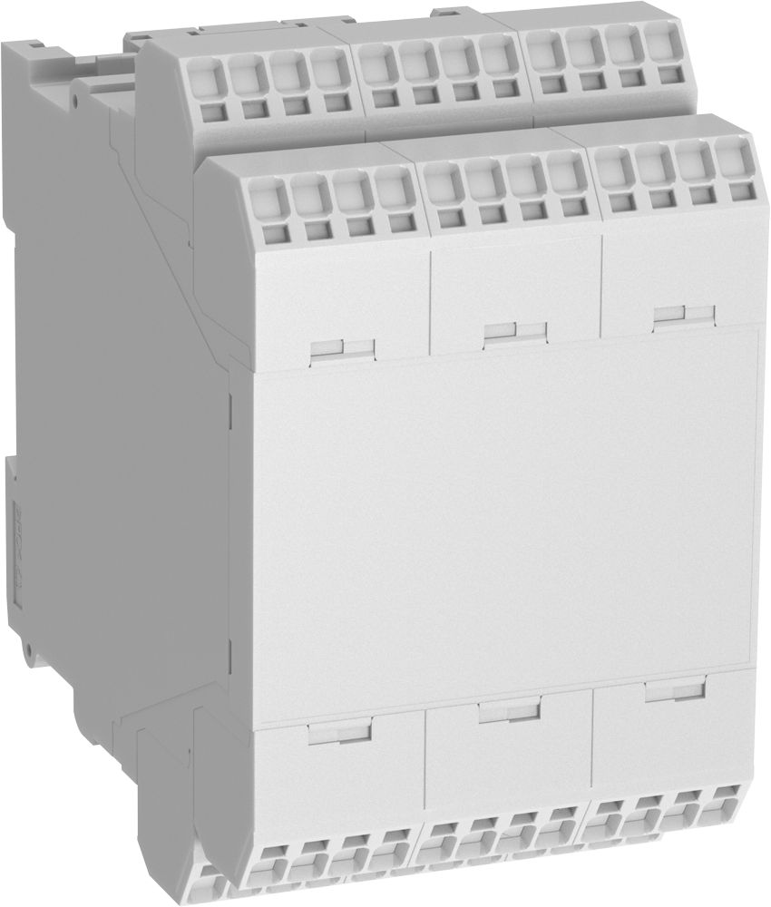
• Max. 16 / 32 / 48 / 64 spring cage clamps
• Large, variable front plate surface
• Max. current carrying capacity 16 A
• Machine soldered terminal block,
use of heat-resistant plastic means no
cover for the terminal block facing the
soldering bath is required
• Easy and quick connecting of conductors:
solid wire and flexible wire with
end ferrule can be inserted directly
(saving of time in comparsion to screw
terminals: 50 - 80 %)
• Easy removing of conductors (put in a
screwdriver according to DIN 5264-A 0.5 x 3)
• High spring force for a secure connection
• Printed circuit board density t = 1.5 mm
and 1 mm possible
Товар в корзине.
Перейти в корзину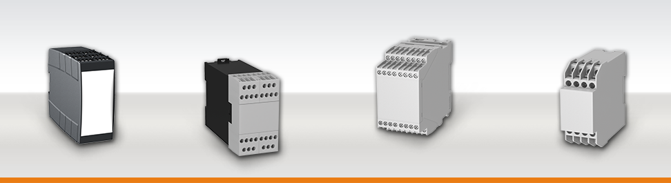
7 different enclosure series for installation in industrial cabinets
You are looking for an universal enclosure solution for your electronic? We offer the suitable enclosure for your application. Dold now offers 7 different Series for installation in industrial cabinets / distribution boards which means that, no matter what the application, there is always an enclosure for the job. All these Series provide several width sizes, screw-terminals or plug-in terminals, different colours and customised options.
Свяжитесь с нами
Если вы не нашли нужной информации на сайте или у вас остались вопросы по товарам, оставьте заявку на бесплатную консультацию, и мы вам перезвоним





 Ответ от производителя может занять до 5 дней и более.