Solenoid interlock Schmersal
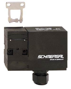
• Individual coding
• Coding level "High" according to ISO 14119
• 90 mm x 84 mm x 30 mm
• Compact design
• Interlock with protection against incorrect locking.
• Long life
• High holding force
• 1 Cable entry M 20 x 1.5
• left-hand model
• For very smal actuating radii in line with or at 90° to the plane of the actuator
• IDC method of termination
• Manual release
• Individual coding
• Coding level "High" according to ISO 14119
• 90 mm x 84 mm x 30 mm
• Compact design
• Interlock with protection against incorrect locking.
• Long life
• High holding force
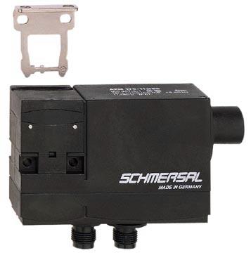
• right-hand model
• For very smal actuating radii in line with or at 90° to the plane of the actuator
• Connector M12, 4-pole
• A- and B-coding of the connectors
• Manual release from side
• Individual coding
• Coding level "High" according to ISO 14119
• 90 mm x 84 mm x 30 mm
• Compact design
• Interlock with protection against incorrect locking.
• Long life
• High holding force
• right-hand model
• For very smal actuating radii in line with or at 90° to the plane of the actuator
• Connector M12, 4-pole
• A- and B-coding of the connectors
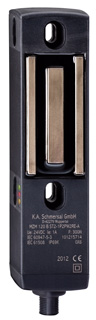
• Thermoplastic enclosure
• Safety switches must be used as end stop
• 40 mm x 179 mm x 40 mm
• Electronic contact-free, coded system
• Variably adjustable latching
• 3 LEDs to show operating conditions
• Sensor technology permits an offset between actuator and interlock of ± 5 mm vertically and ± 3 mm horizontally
• Intelligent diagnosis
• Self-monitoring series-wiring of 31 sensors
• connector plug M12, 8-pole
• Power to lock
• enabling signal, when safety guard closed and locked (without force monitoring)
• Thermoplastic enclosure
• Safety switches must be used as end stop
• 40 mm x 179 mm x 40 mm
• Electronic contact-free, coded system
• Variably adjustable latching
• 3 LEDs to show operating conditions
• Sensor technology permits an offset between actuator and interlock of ± 5 mm vertically and ± 3 mm horizontally
• Intelligent diagnosis
• Self-monitoring series-wiring of 31 sensors
• connector plug M12, 8-pole
• Power to lock
• serial diagnostic output
• enabling signal, when safety
• Thermoplastic enclosure
• Safety switches must be used as end stop
• 40 mm x 179 mm x 40 mm
• Electronic contact-free, coded system
• Variably adjustable latching
• 3 LEDs to show operating conditions
• Sensor technology permits an offset between actuator and interlock of ± 5 mm vertically and ± 3 mm horizontally
• Intelligent diagnosis
• Self-monitoring series-wiring of 31 sensors
• connector plug M12, 8-pole
• Power to lock
• enabling signal, when safety
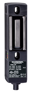
• Automatic latching
• Solenoid interlocks (for the protection of man) with innovating and unique operating principle
• 40 mm x 179 mm x 40 mm
• Electronic contact-free, coded system
• Thermoplastic enclosure
• Max. length of the sensor chain 200 m
• 3 LEDs to show operating conditions
• Sensor technology permits an offset between actuator and interlock of ± 5 mm vertically and ± 3 mm horizontally
• Intelligent diagnosis
• Self-monitoring series-wiring of 31 sensors
• Patented
• Connector M12, 8-pole
• Power to lock
• Solenoid interlocks (for the protection of man) with innovating and unique operating principle
• 40 mm x 179 mm x 40 mm
• Electronic contact-free, coded system
• Thermoplastic enclosure
• Max. length of the sensor chain 200 m
• 3 LEDs to show operating conditions
• Sensor technology permits an offset between actuator and interlock of ± 5 mm vertically and ± 3 mm horizontally
• Intelligent diagnosis
• Self-monitoring series-wiring of 31 sensors
• Patented
• Guard locking monitored
• Connector M23, 8+1-pole
• Power to lock
• Automatic latching
• Solenoid interlocks (for the protection of man) with innovating and unique operating principle
• 40 mm x 179 mm x 40 mm
• Electronic contact-free, coded system
• Thermoplastic enclosure
• Max. length of the sensor chain 200 m
• 3 LEDs to show operating conditions
• Sensor technology permits an offset between actuator and interlock of ± 5 mm vertically and ± 3 mm horizontally
• Intelligent diagnosis
• Self-monitoring series-wiring of 31 sensors
• Patented
• Connector M23, 8+1-pole
• Power to lock
• Solenoid interlocks (for the protection of man) with innovating and unique operating principle
• 40 mm x 179 mm x 40 mm
• Electronic contact-free, coded system
• Thermoplastic enclosure
• Max. length of the sensor chain 200 m
• 3 LEDs to show operating conditions
• Sensor technology permits an offset between actuator and interlock of ± 5 mm vertically and ± 3 mm horizontally
• Intelligent diagnosis
• Self-monitoring series-wiring of 31 sensors
• Patented
• Guard locking monitored
• Connector M23, 8+1-pole
• Power to lock
• serial diagnostic output
• Automatic latching
• Solenoid interlocks (for the protection of man) with innovating and unique operating principle
• 40 mm x 179 mm x 40 mm
• Electronic contact-free, coded system
• Thermoplastic enclosure
• Max. length of the sensor chain 200 m
• 3 LEDs to show operating conditions
• Sensor technology permits an offset between actuator and interlock of ± 5 mm vertically and ± 3 mm horizontally
• Intelligent diagnosis
• Self-monitoring series-wiring of 31 sensors
• Patented
• Connector M23, 8+1-pole
• Power to lock
• serial diagnostic output
• Automatic latching
• Solenoid interlocks (for the protection of man) with innovating and unique operating principle
• 40 mm x 179 mm x 40 mm
• Electronic contact-free, coded system
• Thermoplastic enclosure
• Max. length of the sensor chain 200 m
• 3 LEDs to show operating conditions
• Sensor technology permits an offset between actuator and interlock of ± 5 mm vertically and ± 3 mm horizontally
• Intelligent diagnosis
• Self-monitoring series-wiring of 31 sensors
• Patented
• Connector M12, 8-pole
• Power to lock
• Permanent magnet
Application:
AZM range solenoid interlocks, operating in combination with control elements of a machine, e.g. fail-safe standstill monitors or fail-safe delay timers, ensure that sliding, hinged and removable guarding devices, such as grids, hoods or doors, cannot be opened until hazardous conditions (e.g. running-down movements) have come to an end.
These solenoid interlocks are also used for cases in which the opening of a guarding device represents a non-permissible intrusion in a production process.
Design and mode of operation:
On the AZM range solenoid interlocks, the switching element with interlock is not physically connected to the actuator but functionally brought together or seperated on switching. When the guard device is opened in the uninterlocked condition, the actuator is seperated from the base unit. In the process, NC contacts are positively opened and NO contacts closed.
Interlocking is carried out by means of a blocking bolt / latching bolt. This latching bolt blocks the actuator so that it cannot be withdrawn from the interlock. The machine control circuit is only enabled when the actuator has been fed into the interlock and the latching bolt is in the blocking position. This is ensured by contact monitoring of the latching bolt.
There are two modes of interlocking. In the case of "Power to unlock", the latching bolt is held in the interlock by spring pressure. When the de-interlocking coil is energised, the interlock is removed and the NC contacts opened. The guarding device can be opened. For "Power to lock 1)", the mode of operation is reversed.
The AZM 161, 170, 190 and 415 solenoid interlocks are fitted with protection against incorrect locking. Depending on the type of unit, an individual coding of the actuator are possible.
The solenoid interlocks can be fitted in any desired mounting position. Protection class of the solenoid interlocks is IP 54, IP 65 or IP 67.
1) In accordance with the policy of the German Technical Assessors, these interlock may only be used after a thorough evaluation of the accident risk, since the guarding device can immediately be opened on failure of the electrical power supply.


 Ответ от производителя может занять до 5 дней и более.

