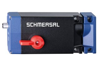
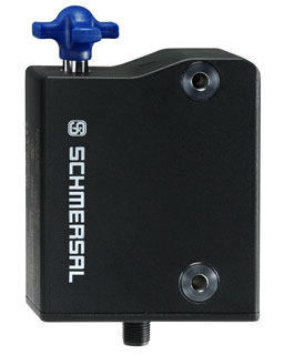
Solenoid interlock Schmersal
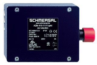
• Interlock with protection against incorrect locking.
• Robust design
• Long life
• 2 cable entries M 20 x 1.5
• Cut clamp termination
• Adjustable ball latch to 400 N
• 2 switches in one enclosure
• Problem-free opening of stressed doors by means of bell-crank system
• Ex version available
• Emergency exit
• 152 mm x 100 mm x 46,5 mm
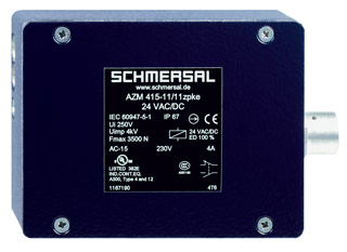
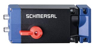
• Interlock with protection against incorrect locking.
• Robust design
• Long life
• 2 cable entries M 20 x 1.5
• Cut clamp termination
• Adjustable ball latch to 400 N
• 2 switches in one enclosure
• Problem-free opening of stressed doors by means of bell-crank system
• Ex version available
• Manual release
• 141 mm x 100 mm x 46,5 mm
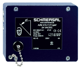
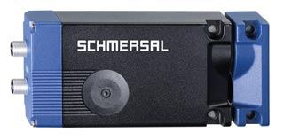
• Interlock with protection against incorrect locking.
• Robust design
• Long life
• 2 cable entries M 20 x 1.5
• Cut clamp termination
• Adjustable ball latch to 400 N
• 2 switches in one enclosure
• Problem-free opening of stressed doors by means of bell-crank system
• Ex version available
• Manual release
• 141 mm x 100 mm x 56,5 mm
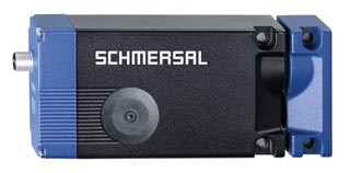
• Interlock with protection against incorrect locking.
• Robust design
• Long life
• 2 cable entries M 20 x 1.5
• Cut clamp termination
• Adjustable ball latch to 400 N
• 2 switches in one enclosure
• Problem-free opening of stressed doors by means of bell-crank system
• Ex version available
• Emergency exit
• 152 mm x 100 mm x 46,5 mm
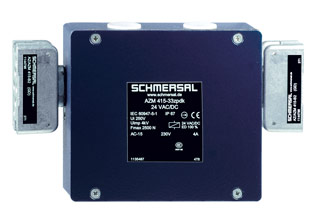
• Interlock with protection against incorrect locking.
• Robust design
• Long life
• 2 cable entries M 20 x 1.5
• Cut clamp termination
• Ball latch for each door, individually adjustable up to 400 N
• 3 switches in one enclosure
• Spring-loaded actuators
• for double doors
• 141 mm x 125 mm x 46,5 mm
• Clamping force 10.000 N
• Release possible against lateral forces up to 300 N
• PL e / cat. 4 / SIL 3 for interlocking and guard locking function
• Two-channel input signal of the guard locking function
• Operation on P/P- and P/N-switching outputs
• High tolerance to door misalignment
• Repeated individual coding with RFID technology
• Coding level "High" according to ISO 14119
• Connector M12, 8-pole
• Guard locking monitored
• 1 Diagnostic output
• Emergency exit
• Clamping force 10.000 N
• Release possible against lateral forces up to 300 N
• PL e / cat. 4 / SIL 3 for interlocking and guard locking function
• Two-channel input signal of the guard locking function
• Operation on P/P- and P/N-switching outputs
• High tolerance to door misalignment
• Repeated individual coding with RFID technology
• Coding level "High" according to ISO 14119
• 2 Connector M12, 8- and 5-poles
• Guard locking monitored
• 2 Diagnostic outputs
• Emergency exit
• Electric manual release with auxiliary voltage
• Clamping force 10.000 N
• Release possible against lateral forces up to 300 N
• PL e / cat. 4 / SIL 3 for interlocking and guard locking function
• Two-channel input signal of the guard locking function
• Operation on P/P- and P/N-switching outputs
• High tolerance to door misalignment
• Universal coding with RFID technology
• Connector M12, 8-pole
• Guard locking monitored
• 1 Diagnostic output
• Emergency exit
• Clamping force 10.000 N
• Release possible against lateral forces up to 300 N
• PL e / cat. 4 / SIL 3 for interlocking and guard locking function
• Two-channel input signal of the guard locking function
• Operation on P/P- and P/N-switching outputs
• High tolerance to door misalignment
• Repeated individual coding with RFID technology
• Coding level "High" according to ISO 14119
• 2 Connector M12, 8- and 5-poles
• Guard locking monitored
• 2 Diagnostic outputs
• manual release
• Electric manual release with auxiliary voltage
• Clamping force 10.000 N
• Release possible against lateral forces up to 300 N
• PL e / cat. 4 / SIL 3 for interlocking and guard locking function
• Two-channel input signal of the guard locking function
• Operation on P/P- and P/N-switching outputs
• High tolerance to door misalignment
• Individual coding with RFID technology
• Coding level "High" according to ISO 14119
• 2 Connector M12, 8- and 5-poles
• Guard locking monitored
• 2 Diagnostic outputs
• Emergency exit
• Electric manual release with auxiliary voltage
• Clamping force 10.000 N
• Release possible against lateral forces up to 300 N
• PL e / cat. 4 / SIL 3 for interlocking and guard locking function
• Two-channel input signal of the guard locking function
• Operation on P/P- and P/N-switching outputs
• High tolerance to door misalignment
• Universal coding with RFID technology
• 2 Connector M12, 8- and 5-poles
• Guard locking monitored
• 2 Diagnostic outputs
• Emergency exit
• Electric manual release with auxiliary voltage
• Clamping force 10.000 N
• Release possible against lateral forces up to 300 N
• PL e / cat. 4 / SIL 3 for interlocking and guard locking function
• Two-channel input signal of the guard locking function
• Operation on P/P- and P/N-switching outputs
• High tolerance to door misalignment
• Individual coding with RFID technology
• Coding level "High" according to ISO 14119
• 2 Connector M12, 8- and 5-poles
• Guard locking monitored
• 2 Diagnostic outputs
• manual release
• Electric manual release with auxiliary voltage
• Clamping force 10.000 N
• Release possible against lateral forces up to 300 N
• PL e / cat. 4 / SIL 3 for interlocking and guard locking function
• Two-channel input signal of the guard locking function
• Operation on P/P- and P/N-switching outputs
• High tolerance to door misalignment
• Repeated individual coding with RFID technology
• Coding level "High" according to ISO 14119
• Connector M12, 8-pole
• Guard locking monitored
• 1 Diagnostic output
• manual release
• Clamping force 10.000 N
• Release possible against lateral forces up to 300 N
• PL e / cat. 4 / SIL 3 for interlocking and guard locking function
• Two-channel input signal of the guard locking function
• Operation on P/P- and P/N-switching outputs
• High tolerance to door misalignment
• Individual coding with RFID technology
• Coding level "High" according to ISO 14119
• Connector M12, 8-pole
• Guard locking monitored
• 1 Diagnostic output
• Emergency exit
• Clamping force 10.000 N
• Release possible against lateral forces up to 300 N
• PL e / cat. 4 / SIL 3 for interlocking and guard locking function
• Two-channel input signal of the guard locking function
• Operation on P/P- and P/N-switching outputs
• High tolerance to door misalignment
• Universal coding with RFID technology
• 2 Connector M12, 8- and 5-poles
• Guard locking monitored
• 2 Diagnostic outputs
• manual release
• Electric manual release with auxiliary voltage
• Clamping force 10.000 N
• Release possible against lateral forces up to 300 N
• PL e / cat. 4 / SIL 3 for interlocking and guard locking function
• Two-channel input signal of the guard locking function
• Operation on P/P- and P/N-switching outputs
• High tolerance to door misalignment
• Individual coding with RFID technology
• Coding level "High" according to ISO 14119
• Connector M12, 8-pole
• Guard locking monitored
• 1 Diagnostic output
• manual release
• Clamping force 10.000 N
• Release possible against lateral forces up to 300 N
• PL e / cat. 4 / SIL 3 for interlocking and guard locking function
• Two-channel input signal of the guard locking function
• Operation on P/P- and P/N-switching outputs
• High tolerance to door misalignment
• Universal coding with RFID technology
• Connector M12, 8-pole
• Guard locking monitored
• 1 Diagnostic output
• manual release
• Thermoplastic enclosure
• RFID-technology for needs-based protection against tampering
• 3 different directions of actuation
• Compact design
• 3 LEDs to show operating conditions
• Suitable for hinged and sliding guards
• Series-wiring
• Manual release
• Individual coding with RFID technology
• Coding level "High" according to ISO 14119
• Connector M12, 8-pole
• Power to lock
• Actuator monitored
• Diagnostic output
• Thermoplastic enclosure
• RFID-technology for needs-based protection against tampering
• 3 different directions of actuation
• Compact design
• 3 LEDs to show operating conditions
• Suitable for hinged and sliding guards
• Series-wiring
• Manual release
• Individual coding with RFID technology
• Coding level "High" according to ISO 14119
• Connector M12, 8-pole
• Power to lock
• Guard locking monitored
• Diagnostic output
• Thermoplastic enclosure
• RFID-technology for needs-based protection against tampering
• 3 different directions of actuation
• Compact design
• 3 LEDs to show operating conditions
• Suitable for hinged and sliding guards
• Series-wiring
• Manual release
• Universal coding with RFID technology
• Connector M12, 8-pole
• Power to lock
• Guard locking monitored
• Diagnostic output
Application:
AZM range solenoid interlocks, operating in combination with control elements of a machine, e.g. fail-safe standstill monitors or fail-safe delay timers, ensure that sliding, hinged and removable guarding devices, such as grids, hoods or doors, cannot be opened until hazardous conditions (e.g. running-down movements) have come to an end.
These solenoid interlocks are also used for cases in which the opening of a guarding device represents a non-permissible intrusion in a production process.
Design and mode of operation:
On the AZM range solenoid interlocks, the switching element with interlock is not physically connected to the actuator but functionally brought together or seperated on switching. When the guard device is opened in the uninterlocked condition, the actuator is seperated from the base unit. In the process, NC contacts are positively opened and NO contacts closed.
Interlocking is carried out by means of a blocking bolt / latching bolt. This latching bolt blocks the actuator so that it cannot be withdrawn from the interlock. The machine control circuit is only enabled when the actuator has been fed into the interlock and the latching bolt is in the blocking position. This is ensured by contact monitoring of the latching bolt.
There are two modes of interlocking. In the case of "Power to unlock", the latching bolt is held in the interlock by spring pressure. When the de-interlocking coil is energised, the interlock is removed and the NC contacts opened. The guarding device can be opened. For "Power to lock 1)", the mode of operation is reversed.
The AZM 161, 170, 190 and 415 solenoid interlocks are fitted with protection against incorrect locking. Depending on the type of unit, an individual coding of the actuator are possible.
The solenoid interlocks can be fitted in any desired mounting position. Protection class of the solenoid interlocks is IP 54, IP 65 or IP 67.
1) In accordance with the policy of the German Technical Assessors, these interlock may only be used after a thorough evaluation of the accident risk, since the guarding device can immediately be opened on failure of the electrical power supply.


 Ответ от производителя может занять до 5 дней и более.

