SINAMICS S120 Cabinet Modules Siemens
- Customized solutions
- Order-specific integration engineering
- Supplementary system components
- Customer terminal block -X55
- Description of the options
- Auxiliary Power Supply Modules
- Central Braking Modules
- Motor Modules chassis format
- Motor Modules Booksize Cabinet Kits format
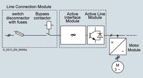
- Active Line Modules including Active Interface Modules
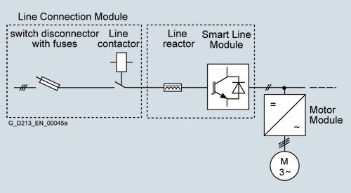
- Smart Line Modules
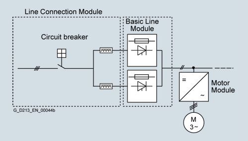
- Basic Line Modules
- Line Connection Modules
Область применения
SINAMICS S120 Cabinet Modules have been specially developed to allow simple configuration of multi-motor systems. They are used for applications where several motors must be coordinated to realize a drive task as multi-motor drives in a drive lineup. Examples of such applications include:
- Paper machines
- Rolling mills
- Hoisting gear
- Test bays
Обзор
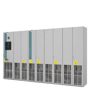
SINAMICS S120 Cabinet Modules are components forming part of a modular cabinet system for multi-motor drives with a central line infeed and a common DC busbar of the type typically used in, for example, paper-making machines, roller mills, test stands, or hoisting gear. As standard, they are installed side by side in a row. Other installation types (e.g. back to back) are possible on request. They include the chassis units from the SINAMICS S120 series in booksize format (Motor Modules) and chassis format, thus making the range an ideal supplement to the SINAMICS G150 and SINAMICS S150 cabinet unit series for single-motor drives.
All drive components, from the line infeed to the motor-side inverters, are configured in a clear, compact layout in the individual Cabinet Modules. They can be combined with great flexibility and can be optimally adapted to customer-specific requirements thanks to a comprehensive array of options.
The main components of the system are as follows:
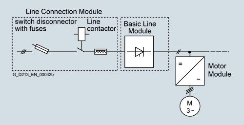
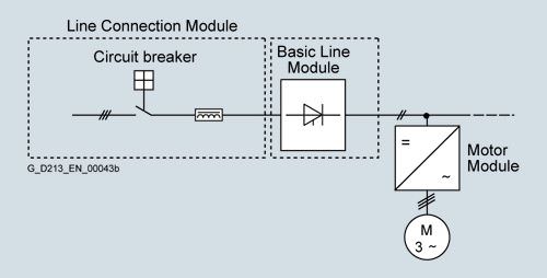
- Line Connection Modules with line-side components such as contactors, fuses and circuit breakers, as well as line reactors for Basic Line Modules.
- Line Modules for the infeed in the following variations:
- Basic Line Modules for two-quadrant operation
- Smart Line Modules for four-quadrant operation
- Active Line Modules for four-quadrant operation with negligible line harmonics
- Central Braking Modules for braking operation
- The following types of Motor Modules:
- Booksize Kit
- Chassis
- Control Units
- Auxiliary Power Supply Modules
Standardized interfaces for both the power and the control connections facilitate configuration and installation. Communication between the power modules and the central Control Unit takes place via DRIVE-CLiQ, the internal drive serial interface.
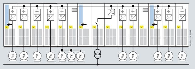
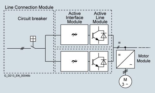
Example of a drive line-up with SINAMICS S120 Cabinet Modules for a multi-motor drive
The following table provides an overview of the voltage ranges and power ratings of the SINAMICS S120 Cabinet Modules that are available:
| Line voltage | Input current | DC link voltage | DC link current | Output current | Power range |
|---|---|---|---|---|---|---|
Line Connection Modules | 380 … 480 V 3 AC | 250 … 3200 A | – | – | – | – |
500 … 690 V 3 AC | 280 … 3200 A | – | – | – | – | |
Basic Line Modules | 380 … 480 V 3 AC | 365 … 1630 A | 510 … 650 V | 420 … 1880 A | – | 200 … 900 kW |
500 … 690 V 3 AC | 260 … 1580 A | 675 … 930 V | 300 … 1880 A | – | 250 … 1500 kW | |
Smart Line Modules | 380 … 480 V 3 AC | 463 … 1430 A | 510 … 650 V | 550 … 1700 A | – | 250 … 800 kW |
500 … 690 V 3 AC | 463 … 1430 A | 675 … 930 V | 550 … 1700 A | – | 450 … 1400 kW | |
Active Line modules | 380 … 480 V 3 AC | 210 … 1405 A | 540 … 720 V | 235 … 1574 A | – | 132 … 900 kW |
500 … 690 V 3 AC | 575 … 1270 A | 710 … 1035 V | 644 … 1422 A | – | 560 … 1400 kW | |
Motor Modules booksize | 380 … 480 V 3 AC | – | 510 … 720 V | 3,6 … 200 A | 3 … 200 A | 1,6 … 107 kW |
Motor Modules chassis | 380 … 480 V 3 AC | – | 510 … 720 V | 252 … 1686 A | 210 … 1405 A | 110 … 800 kW |
500 … 690 V 3 AC | – | 675 … 1035 V | 102 … 1524 A | 85 … 1270 A | 75 … 1200 kW | |
Central Braking Modules | 380 … 480 V 3 AC | – | 510 ... 720 V | – | – | 500 ... 1000 kW |
500 ... 600 V 3 AC | – | 675 ... 900 V | – | – | 550 ... 1100 kW | |
660 … 690 V 3 AC | – | 890 ... 1035 V | – | – | 630 ... 1200 kW | |
Auxiliary Power Supply Modules | 380 … 690 V 3 AC | 125 ... 250 A | – | – | – | – |
The power can be increased by connecting up to four identical modules in parallel.
Дизайн
They have been designed with a zone concept and therefore offer the highest possible level of operational reliability. EMC measures have been rigorously implemented. With the help of simulated conditions, partitions have been designed to act as air guides and heat dissipation units.
Special measures used in the construction of the cabinets ensure that they remain mechanically durable over their entire life cycle.
Attention has been paid to providing a wide range of cable routing options and special design concepts are applied consistently to broaden the scope of application and simplify servicing. The units have all the necessary connections and connecting elements. Thanks to their carefully considered configuration concept, cabinets are shipped in a ready-to-connect state or, in the case of multiple transport units, have been prepared for quick assembly. The selection you make is supported by an extensive range of options, harmonized and coordinated to various applications.
All components, from individual parts to the ready-to-connect cabinet, undergo rigorous testing throughout the entire production process. This guarantees a high level of functional reliability during installation and commissioning, as well as in operation.
The design of replaceable components is based on the principle that they must be quick and easy to change. In addition, the "SparesOnWeb" Internet tool makes it easy to view the spare parts that are available for the particular order 1).
1) The properties of the SINAMICS S120 Cabinet Modules described in this catalog are not transferable to cabinet units constructed to meet the requirements of specific applications.
Line Modules
Power is fed to the drive line-up via Line Modules, which generate a DC voltage from the line voltage and, therefore, supply energy to the Motor Modules connected to the DC link. They are suitable for connection to grounded TN/TT and non-grounded IT systems.
The Line Modules are connected to the line supply system via Line Connection Modules and are equipped as standard according to Category C3. Category C3 is part of the "second environment" (in accordance with EN 61800-3). The second environment are locations outside residential areas or industrial sites which are supplied from the medium-voltage network via a separate transformer.
The range of Line Modules has power ratings from 132 kW to 900 kW (380 V to 480 V) and from 250 kW to 1500 kW (500 V to 690 V). Furthermore, up to four identical Line Modules can be connected in parallel in order to increase the power rating.
For a compact configuration, Line Connection Modules up to input currents of 3200 A are available. Two Line Modules can be operated in parallel on these Line Connection Modules.
The following types of Line Module are available:
- Basic Line Modules
- Smart Line Modules
- Active Line Modules
Basic Line Modules
Basic Line Modules are designed only for infeed operation, i.e. they are not capable of recovering energy to the mains supply.
If regenerative energy is produced, e.g. when the drives brake, then it must be converted to heat by means of a Braking Module and a braking resistor.
When a Basic Line Module is used as the infeed, a line reactor appropriate to the supply conditions must be installed. Line reactors are generally required if two or more Basic Line Modules are operated in parallel on a common supply system in order to increase power.
For this reason, line reactors are installed in the appropriate Line Connection Module as standard.
If, for example, a converter transformer is used to connect to the line supply (12-pulse operation), line reactors might not be required and they can be optionally omitted (order code L22).
In the case of parallel connection, versions with line-side fuses are available for selective protection of the individual Basic Line Modules.
Smart Line Modules
Smart Line Modules can supply energy to the DC link and return regenerative energy to the supply system. Braking Modules and braking resistors are required only if the drives need to be decelerated in a controlled manner after a power failure – i.e. when energy cannot be regenerated into the line supply. When a Smart Line Module is used as the infeed, the necessary line reactor is included in the device as standard.
Active Line Modules
Active Line Modules can supply energy and return regenerative energy to the supply system. Braking Modules and braking resistors are required only if the drives need to be decelerated in a controlled manner after a power failure – i.e. when energy cannot be regenerated into the line supply.
In contrast to Basic Line Modules and Smart Line Modules, however, Active Line Modules generate a regulated DC voltage which remains constant despite fluctuations in the line voltage. However, in this case, the line voltage must remain within the permissible tolerance range. Active Line Modules draw a virtually sinusoidal current from the supply which limits any harmful harmonics.
Active Line Modules must always be used in conjunction with an Active Interface Module. Active Interface Modules include the required pre-charging circuit for the Active Line Module in addition to a Clean Power Filter. For SINAMICS S120 Cabinet Modules, these two components are always regarded as a single unit.
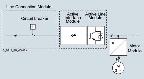
In the example, two units comprising an Active Interface Module and Active Line Module are connected in parallel to jointly supply the DC link.
DC link components
Braking Modules enable braking resistors to absorb the regenerative energy produced during drive deceleration, which is then converted into heat.
Braking Modules as a Line Module or Motor Module option
For lower braking powers, Braking Modules are available with continuous braking powers up to 50 kW. These Braking Modules are ordered as an option for the Line Modules and Motor Modules (order codes L61/L64 (25 kW) or L62/L65 (50 kW), refer to the description of the options).
Central Braking Modules
For higher continuous braking powers, separate Central Braking Modules are available. These modules are used centrally in the drive line-up.
Motor Modules
There are two different types of Motor Module available with the SINAMICS S120 Cabinet Modules drive system.
Booksize Base Cabinets with Booksize Cabinet Kits
Motor Modules at the low end of the power range from 1.6 kW to 107 kW (380 V to 480 V) can be implemented as Booksize Cabinet Kits installed in Booksize Base Cabinets. In the 1.6 kW to 9.7 kW power range, Booksize Cabinet Kits are available as Double Motor Modules, which combine two inverters in a single module.
Chassis Cabinets
Each Chassis Cabinet is fitted with one SINAMICS S120 Motor Module in chassis format and covers the power range from 75 kW to 1200 kW (380 V to 480 V or 500 V to 690 V). The power rating can be extended up to approx. 4500 kW by connecting up to four Motor Modules in the chassis format in parallel.
SINAMICS S120 Motor Modules, chassis format and Cabinet Modules can also be used as a braking module, if, instead of a motor, a 3-phase braking resistor is connected.
For more detailed information, please refer to the SINAMICS Low Voltage Engineering Manual.
System structure
Line Modules are coupled with the various Motor Modules by means of prefabricated busbar sets with different current carrying capacities.
All standard busbars, as well as electronics components, are protected against environmental influences. This is achieved through the use of nickel-plated copper bars and painted modules throughout.
A special, standard auxiliary power supply system supplies the individual Cabinet Modules with the required auxiliary voltages for the power components, fans and 24 V loads.
These voltages are preferably generated using an auxiliary power supply module. Additional supply possibilities are available using the K76 option (auxiliary power supply generation in the Line Connection Module) or using an external supply in the auxiliary power supply system.
The auxiliary power supply system comprises an auxiliary power supply module with two terminal blocks and a 24 V DC fuse as well as the required connecting cables. It is supplied completely assembled and ready to operate. Only the cable connections to the adjacent Cabinet Module must be established on-site.
Communication between the Control Unit, power units and other active SINAMICS components is realized via DRIVE-CLiQ connections.
DRIVE-CLiQ is an internal serial interface of the drive that enables fast and easy configuration of the complete drive line-up with prefabricated cables in varying lengths.
The Cabinet Modules can be optionally supplied in pre-configured transport units up to a total length of 2400 mm . This option is recommended in particular for Line Modules together with Line Connection Modules since, in this case, the Line Connection Module must be equipped with a pre-charging DC link or line reactors (depending on the type of Line Module), in addition to the electrical interface (busbar). Transport units enable the various devices to be quickly and easily assembled on-site.
Varnished PCBs
The following drive units are equipped as standard with varnished PCBs:
- Chassis format units
- Control Units
- Sensor Modules
- Terminal Modules
- Advanced Operator Panel (AOP30)
The varnish coating on the modules protects the sensitive SMD components against corrosive gases, chemically active dust and moisture.
Nickel-plated busbars
All of the copper busbars used in the converter cabinets are nickel-plated in order to achieve the best possible immunity to environmental effects. Further, the bare copper connections do not have to be cleaned for customer connections.
Note: For technical reasons, some parts of the copper busbars are not nickel-plated for some of the options.
Degrees of protection of Cabinet Modules
The EN 60529 standard covers the protection of electrical equipment by means of housings, covers or equivalent, and includes:
- Protection of persons against accidental contact with live or moving parts within the housing and protection of the equipment against the ingress of solid foreign matter (touch protection and protection against ingress of solid foreign bodies)
- Protection of the equipment against the ingress of water (water protection)
- Abbreviations for the internationally agreed degrees of protection
The degrees of protection are specified by abbreviations comprising the code letters IP and two digits.
Degree of protection | First code number (touch protection and protection against foreign bodies) | Second code number (protection of the equipment against the ingress of water) |
|---|---|---|
IP20 (Standard) | Protection against solid foreign bodies diameter ≥ 12.5 mm | No water protection |
IP21 (Option M21) | Protection against solid foreign bodies diameter ≥ 12.5 mm | Protected against drip water Vertically falling water drops shall not have a harmful effect. |
IP23 (Option M23) | Protection against solid foreign bodies diameter ≥ 12.5 mm | Protected against spray water Water sprayed on both sides of the vertical at an angle of up to 60° shall not have a harmful effect. |
IP43 (Option M43) | Protection against solid foreign bodies diameter ≥ 1 mm | Protected against spray water Water sprayed on both sides of the vertical at an angle of up to 60° shall not have a harmful effect. |
IP54 (Option M54) | Dust protected Ingress of dust is not totally prevented, but dust must not be allowed to enter in such quantities that the functioning or safety of the equipment is impaired. | Protected against splash water Water splashing onto the enclosure from any direction shall not have a harmful effect. |
Cabinet Modules fulfill the criteria for degree of protection IP20 as standard. The other degrees of protection outlined here are available as an option.
Характеристика
Derating data for the chassis format
SINAMICS S120 Cabinet Modules and the associated system components are rated for an ambient temperature of 40 °C and installation altitudes up to 2000 m above sea level.
For ambient temperatures > 40 °C the output current must be reduced. Ambient temperatures above 50 °C are not permissible.
At installation altitudes > 2000 m above sea level, it must be taken into consideration that with increasing height, the air pressure decreases and therefore the air density. As a consequence, the cooling efficiency and the insulation capacity of the air also decrease.
Due to the reduced cooling efficiency, it is necessary, on one hand, to reduce the ambient temperature and on the other hand, to lower heat loss in the Cabinet Module by reducing the output current, whereby ambient temperatures lower than 40 °C may be offset to compensate.
The following table specifies the permissible output current as a function of the installation altitude and ambient temperature for the various degrees of protection (the permissible compensation between installation altitude and the ambient temperatures < 40 °C – air intake temperature at the entry to the Cabinet Module – has been taken into account in the specified values).
The values apply under the precondition that it is a guaranteed that the cooling air, as specified in the technical data, flows through the units as a result of the cabinet arrangement.
As additional measure for installation altitudes from 2000 m up to 5000 m, an isolating transformer is required in order to reduce transient overvoltages according to EN 60664-1.
For additional information, please refer to the SINAMICS Low Voltage Engineering Manual.
Degree of protection | Installation altitude above sea level | Current derating factor (as a % of the rated current) for an ambient/air intake temperature of | ||||||
|---|---|---|---|---|---|---|---|---|
| m | 20 °C | 25 °C | 30 °C | 35 °C | 40 °C | 45 °C | 50 °C |
IP20, IP21, IP23, IP43 | 0 ... 2000 | 100 % | 100 % | 100 % | 100 % | 100 % | 93.3 % | 86.7 % |
2001 ... 2500 | 100 % | 100 % | 100 % | 100 % | 96.3 % | |||
2501 ... 3000 | 100 % | 100 % | 100 % | 98.7 % | ||||
3001 ... 3500 | 100 % | 100 % | 100 % | |||||
3501 ... 4000 | 100 % | 100 % | 96.3 % | |||||
4001 ... 4500 | 100 % | 97.5 % | ||||||
4501 ... 5000 | 98.2 % | |||||||
IP54 | 0 ... 2000 | 100 % | 100 % | 100 % | 100 % | 93.3 % | 86.7 % | 80.0 % |
2001 ... 2500 | 100 % | 100 % | 100 % | 96.3 % | 89.8 % | |||
2501 ... 3000 | 100 % | 100 % | 98.7 % | 92.5 % | ||||
3001 ... 3500 | 100 % | 100 % | 94.7 % | |||||
3501 ... 4000 | 100 % | 96.3 % | 90.7 % | |||||
4001 ... 4500 | 97.5 % | 92.1 % | ||||||
4501 ... 5000 | 93.0 % | |||||||
Current-derating factors for Cabinet Modules as a function of the ambient/air intake temperature, the installation altitude and the degree of protection.
Current derating for SINAMICS S120 Motors Modules, chassis format as a function of the pulse frequency
To reduce motor noise or to increase output frequency, the pulse frequency can be increased relative to the factory setting. When the pulse frequency is increased, the derating factor of the output current must be taken into account. This derating factor must be applied to the currents specified in the technical data.
For additional information, please refer to the SINAMICS Low Voltage Engineering Manual.
Motor Module, chassis format | Type rating | Output current | Derating factor at the pulse frequency | ||||
|---|---|---|---|---|---|---|---|
6SL3720-... | kW | A | 2.5 kHz | 4 kHz | 5 kHz | 7.5 kHz | 8 kHz |
380 … 480 V 3 AC | |||||||
1TE32-1AA3 | 110 | 210 | 95 % | 82 % | 74 % | 54 % | 50 % |
1TE32-6AA3 | 132 | 260 | 95 % | 83 % | 74 % | 54 % | 50 % |
1TE33-1AA3 | 160 | 310 | 97 % | 88 % | 78 % | 54 % | 50 % |
1TE33-8AA3 | 200 | 380 | 96 % | 87 % | 77 % | 54 % | 50 % |
1TE35-0AA3 | 250 | 490 | 94 % | 78 % | 71 % | 53 % | 50 % |
Derating factor of the output current as a function of the pulse frequency for units with a rated pulse frequency of 2 kHz
Motor Module, chassis format | Type rating | Output current | Derating factor at the pulse frequency | ||||
|---|---|---|---|---|---|---|---|
6SL3720-... | kW | A | 2.0 kHz | 2.5 kHz | 4 kHz | 5 kHz | 7.5 kHz |
380 … 480 V 3 AC | |||||||
1TE36-1AA3 | 315 | 605 | 83 % | 72 % | 64 % | 60 % | 40 % |
1TE37-5AA3 | 400 | 745 | 83 % | 72 % | 64 % | 60 % | 40 % |
1TE38-4AA3 | 450 | 840 | 87 % | 79 % | 64 % | 55 % | 40 % |
1TE41-0AA3 | 560 | 985 | 92 % | 87 % | 70 % | 60 % | 50 % |
1TE41-2AA3 | 710 | 1260 | 92 % | 87 % | 70 % | 60 % | 50 % |
1TE41-4AA3 | 800 | 1405 | 97 % | 95 % | 74 % | 64 % | 50 % |
500 … 690 V 3 AC | |||||||
1TG28-5AA3 | 75 | 85 | 93 % | 89 % | 71 % | 60 % | 40 % |
1TG31-0AA3 | 90 | 100 | 92 % | 88 % | 71 % | 60 % | 40 % |
1TG31-2AA3 | 110 | 120 | 92 % | 88 % | 71 % | 60 % | 40 % |
1TG31-5AA3 | 132 | 150 | 90 % | 84 % | 66 % | 55 % | 35 % |
1TG31-8AA3 | 160 | 175 | 92 % | 87 % | 70 % | 60 % | 40 % |
1TG32-2AA3 | 200 | 215 | 92 % | 87 % | 70 % | 60 % | 40 % |
1TG32-6AA3 | 250 | 260 | 92 % | 88 % | 71 % | 60 % | 40 % |
1TG33-3AA3 | 315 | 330 | 89 % | 82 % | 65 % | 55 % | 40 % |
1TG34-1AA3 | 400 | 410 | 89 % | 82 % | 65 % | 55 % | 35 % |
1TG34-7AA3 | 450 | 465 | 92 % | 87 % | 67 % | 55 % | 35 % |
1TG35-8AA3 | 560 | 575 | 91 % | 85 % | 64 % | 50 % | 35 % |
1TG37-4AA3 | 710 | 735 | 87 % | 79 % | 64 % | 55 % | 35 % |
1TG38-1AA3 | 800 | 810 | 97 % | 95 % | 71 % | 55 % | 35 % |
1TG38-8AA3 | 900 | 910 | 92 % | 87 % | 67 % | 55 % | 33 % |
1TG41-0AA3 | 1000 | 1025 | 91 % | 86 % | 64 % | 50 % | 30 % |
1TG41-3AA3 | 1200 | 1270 | 87 % | 79 % | 55 % | 40 % | 25 % |
Derating factor of the output current as a function of the pulse frequency for units with a rated pulse frequency of 1.25 kHz
The following table lists the maximum achievable output frequency as a function of the pulse frequency:
Pulse frequency | Max. achievable output frequency |
|---|---|
1.25 kHz | 100 Hz |
2.00 kHz | 160 Hz |
2.50 kHz | 200 Hz |
≥ 4.00 kHz | 300 Hz |
Derating data for the booksize format
SINAMICS S120 Cabinet Modules with power units, booksize format and the associated system components are rated for an ambient temperature of 40 °C and installation altitudes up to 1000 m above sea level. If SINAMICS S120 Cabinet Modules with power units, booksize format are operated at ambient temperatures higher than 40 °C and/or installation altitudes higher than 1000 m above sea level, then the corresponding derating functions must be taken into account as a function of the ambient temperature and/or the installation altitude. These derating factors are different from the derating factors for the chassis format power units and are listed in Catalog PM 21.
Overload capability
SINAMICS S120 Cabinet Modules have an overload reserve e.g. to handle breakaway torques. If larger surge loads occur, this must be taken into account when configuring. In drives with overload requirements, the appropriate base load current must, therefore, be used as a basis for the required load.
Permissible overload assumes that the drive converter is operated at its base load current before and after the overload occurs, based on a duty cycle duration of 300 s.
For short, repeating load cycles with significant load fluctuations within the load cycle, the appropriate sections in the SINAMICS Low Voltage Engineering Manual must be observed (as PDF file on the CD-ROM provided with the catalog).
Motor Modules chassis format
Motor Modules with power units in the chassis format can be configured on the basis of different base load currents.
The base load current for a low overload IL is the basis for a duty cycle of 110 % for 60 s or 150 % for 10 s.
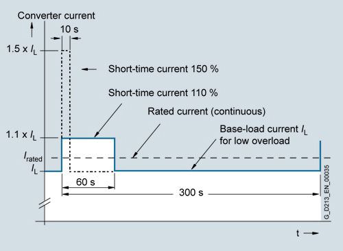
Low overload
The base load current for a high overload IHis the basis for a duty cycle of 150 % for 60 s or 160 % for 10 s.
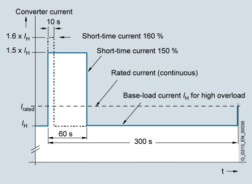
High overload
Motor Modules booksize format
Motor Modules with power units in the booksize format have the following overload capabilities:
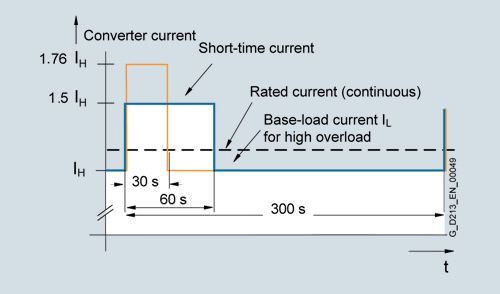
High overload
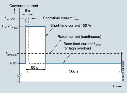
Line Modules chassis format
The base load current for a high overload IH DC is the basis for a duty cycle of 150 % for 60 s or Imax DC for 5 s.
Функции
Communication with higher-level control and customer terminal block
As customer interface to the control system, as standard there is a PROFIBUS interface at the CU320-2 DP Control Unit or a PROFINET interface at the CU320-2 PN Control Unit.
The inputs and outputs available as standard at the customer terminal block -X55 are easy to access and easy to connect.
For additional information, please refer to the SINAMICS Low Voltage Engineering Manual.
Open-loop and closed-loop control functions
SINAMICS S120 has a high-dynamic vector control with speed and current control – with and without speed actual value feedback.
Software and protective functions
The software functions available as standard are described below:
Software and protective functions | Description |
|---|---|
Setpoint input | The setpoint can be input both internally and externally. It is applied internally as a fixed setpoint, motorized potentiometer setpoint or jog setpoint and externally via the communications interface or an analog input on the customer terminal block. The internal fixed setpoint and the motorized potentiometer setpoint can be switched over or adjusted using control commands from any interface. |
Motor identification | The automatic motor identification function makes commissioning faster and easier and optimizes closed-loop control of the drive. |
Ramp-function generator | A user-friendly ramp-function generator with separately adjustable ramp-up and ramp-down times, together with adjustable rounding times in the lower and upper speed ranges, allows the drive to be smoothly accelerated and braked. This results in a good speed control response and plays its role in reducing the stress on the mechanical system. The down ramp can be parameterized separately for a quick stop. |
Vdc max controller | The Vdc max controller automatically prevents overvoltages in the DC link if the down ramp is too short, for example. This may also extend the set ramp-down time. Comment: This function only makes sense for single-axis applications. |
Kinetic buffering (KIP) | For brief line supply failures, the kinetic energy of the rotating drive is used to buffer the DC link and therefore prevents fault trips. The drive converter remains operational as long as the drive can provide regenerative energy as a result of its motion and the DC link voltage does not drop below the shutdown threshold. When the line supply recovers within this time, the drive is again bumplessly accelerated up to its setpoint speed. |
Automatic restart | The automatic restart switches the drive on again when the power is restored after a power failure, and ramps up to the current speed setpoint. |
Flying restart | The flying restart function allows the converter to be switched to a motor that is still turning. |
Technology controller | Using the technology controller (PID controller) function module, level or flow controls and complex tension controls can be implemented, for ex Запрос коммерческого предложения× Сообщение отправлено× В ближайшее время сообщение будет обработано. Письмо с номером обращения отправлено на Ваш почтовый ящик. Спасибо за то, что выбрали Первый ZIP! Что-то пошло не так...× К сожалению, наша система расценила Ваше сообщение как спам. Если это произошло по ошибке, пожалуйста, обратитесь к нам по электронной почте. Приносим извинения за возможные неудобства.  Вы отправляете нам запрос  Если у нас есть прайс-лист, мы отправляем Вам ответ в течение дня. А если у нас нет прайс-листа по запрошенным товарам?     Если у нас нет прайс-листа, мы отправляем запрос производителю.  Ответ от производителя может занять до 5 дней и более. Ответ от производителя может занять до 5 дней и более.  Запрос производителю мы отправляем только для конечных потребителей.  Торгующим организациям коммерческие предложения предоставляются только по прайсовым позициям: Siemens Beckhoff Pepperl+Fuchs Phoenix Contact PILZ Turck Leuze Electronic Endress+Hauser Murr Elektronik Schmersal |