


Поставляем DOLD под заказ



Каталог продукции компании DOLD
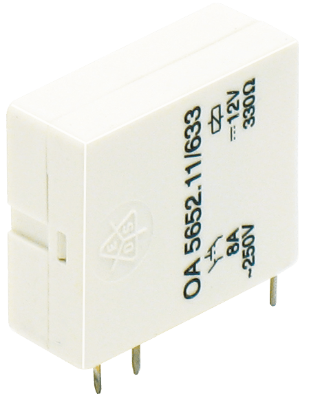 PCB relays (10)
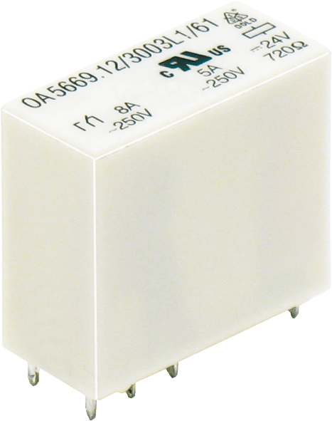
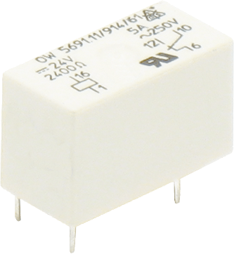 Miniature relays (6)
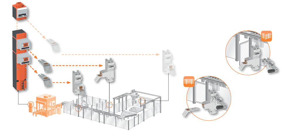
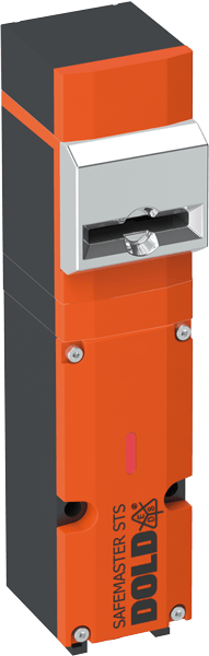 Safety switch (7)
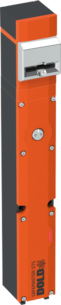 Guard lock (8)
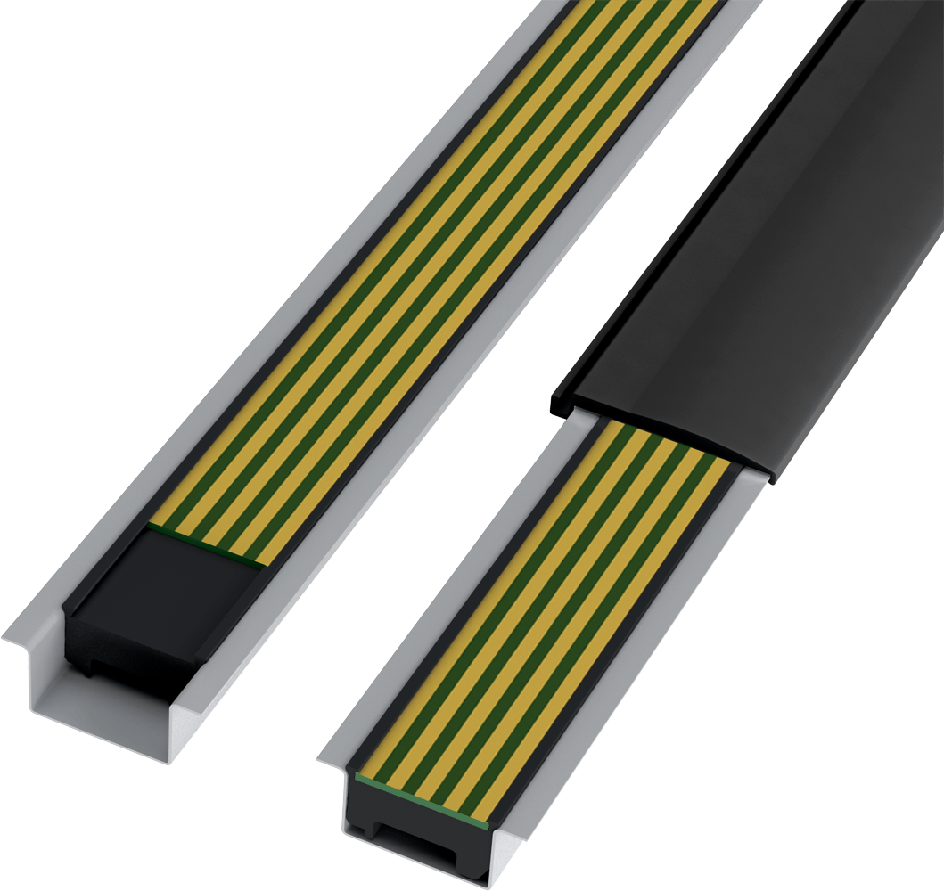 In-Rail-Bus (5)
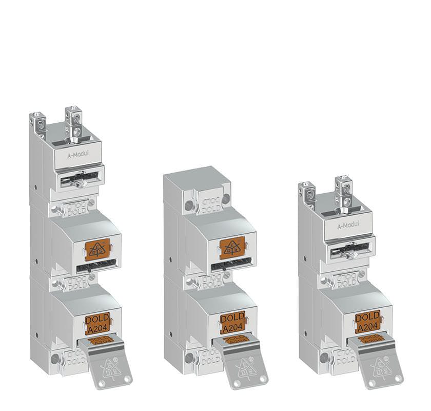 Остальная продукция (38)
- Keys (2)
- Padlock modules (4)
- Locking modules (18)
- Switch modules (6)
- Actuators (9)
- Actuator modules (7)
- Key modules (7)




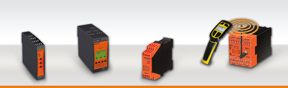
О компании

Dold – Ваш надёжный партнёр в области систем контроля, управления и мониторинга.
Компания Dold одной из первых в мире начала производство распределительных устройств. Сейчас компанией управляет уже третье поколение семьи Долд. Имея более чем полувековой опыт работы, располагая самыми передовыми производственными технологиями и квалифицированным персоналом, на данный момент E. Dold & Sohne KG является ведущим европейским производителем электроники и автоматики.
Вся продукция производится в лучших традициях немецкого качества. На данный момент компания имеет свыше 400 сотрудников, многие из которых работают в ней уже более 20 лет. Именно эти люди хранят весь опыт и знания компании, что имеет гораздо более глубокий смысл, чем избитое слово «ноу-хау».
Благодаря многолетнему опыту работы, компания Dold выпускает широкий спектр продукции, уделяя особое внимание качеству производимого оборудования. Сочетание собственных разработок, технических инноваций, практического опыта и знаний позволяет удовлетворять индивидуальные требования каждого заказчика.
Все товары DOLD
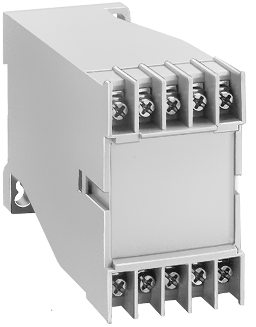
• Max. 10 plus-minus-terminal screws with
self raising terminal washers
• PCBs are easy to install because of
guiding ribs
• Terminal cover for contact protection
complies with VBG 4 as option
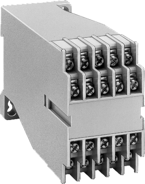
• Max. 20 plus-minus-terminal screws with
self raising terminal washers
• PCBs are easy to install because of
guiding ribs
• Terminal cover for contact protection
complies with VBG 4 as option
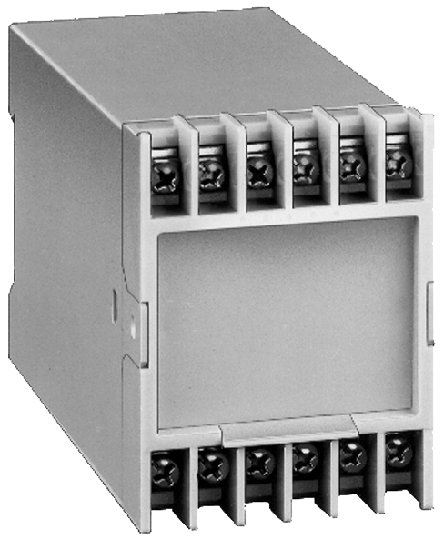
• Max. 12 plus-minus-terminal
screws with self raising terminal washers
• PCBs are easy to install because of
guiding ribs
• Terminal cover for contact protection
complies with VBG 4 as option
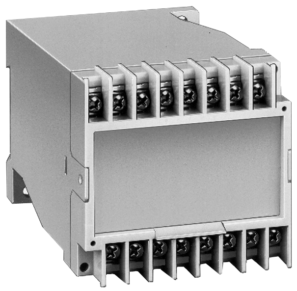
• Max. 16 plus-minus-terminal screws with
self raising terminal washers
• PCBs are easy to install because of
guiding ribs
• Terminal cover for contact protection
complies with VBG 4 as option
• a base section for this enclosure is also
available without screw fixing recesses e.g.
suitable for DIN-rail mounting only
• Changeable Plate as option
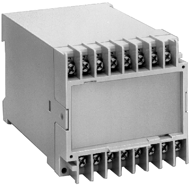
• Max. 16 plus-minus-terminal screws with
self raising terminals washers
• PCBs are easy to install because of
guiding ribs
• Terminal cover for contact protection
complies with VBG 4 as option
• Changeable front plate as option
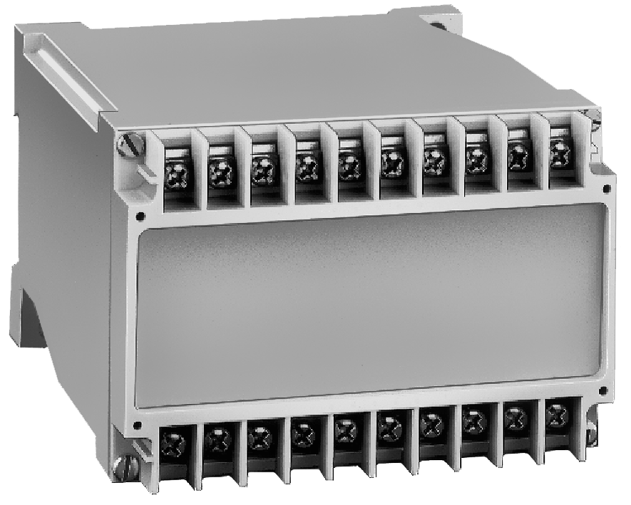
• Max. 20 plus-minus-terminal screws with
self raising terminal washers
• PCBs are easy to install because of
guiding ribs
• Terminal cover for contact protection
complies with VBG 4 as option
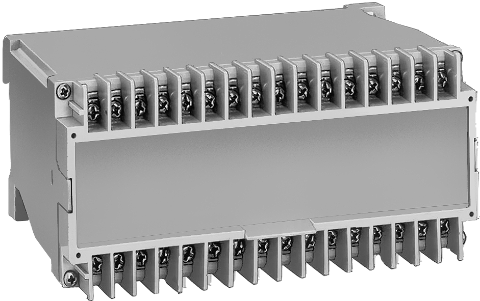
• Max. 32 plus-minus-terminal screws with
self raising terminals washers
• Double contacts for direct insertion of PCB
• PCBs are easy to install because of
guiding ribs
• Terminal cover for contact protection
complies with VBG 4 as option

• High current (5 A per bus pcb-rail)
• Quick and easy mounting in the DIN-rail
• Contour and layout of the bus pcb
can be according to customers'
requirements e.g. defined by the customer
• Designed for standard DIN-rail
dimensions
• Large stand-off to DIN-rail floor allows
the mounting of SMD components on
the bus pcb underside
• The carrier profile is securely fixed by safety
caps (left and right) on the DIN-rail
• Pcb rail "breaks" are possible, e.g. for
operation of bus signals inside
instruments

• High current (5 A per power cable)
• Quick and easy mounting in the DIN-rail
• Contour and layout of the bus pcb
can be according to customers'
requirements e.g. defined by the customer
• Designed for standard DIN-rail
dimensions
• Large stand-off to DIN-rail floor allows
the mounting of SMD components on
the bus pcb underside
• The carrier profile is securely fixed by safety
caps (left and right) on the DIN-rail
• Pcb rail "breaks" are possible, e.g. for
operation of bus signals inside
instruments

• Optionally with max. 4, 6 or 8 captive
plus-minus-terminal screws
• Mounting of pcb's in 2 planes
• With machine solderable double pins
• Optionally with long soldering pin
• Optionally with changeable front plate

• Optionally with max. 4, 6 or 8 captive
plus-minus-terminal screws
• Mounting of pcb's in 2 planes
• With machine solderable double pins
• Optionally with long soldering pin
• Optionally with changeable front plate

• Optionally with max. 4, 6 or 8 captive
plus-minus-terminal screws
• Mounting of pcb's in 2 planes
• With machine solderable double pins
• Optionally with long soldering pin
• Optionally with changeable front plate

• Optionally max. 6, 9 or 12 captive
plus-minus-terminal screws
• Mounting of pcb
• With machine solderable double pins
• Optionally with long soldering pin
• Optionally with Wechselfront

• Optionally max. 6, 9 or 12 captive
plus-minus-terminal screws
• Mounting of pcb
• With machine solderable double pins
• Optionally with long soldering pin
• Optionally with Wechselfront

• Optionally max. 6, 9 or 12 captive
plus-minus-terminal screws
• Mounting of pcb
• With machine solderable double pins
• Optionally with long soldering pin
• Optionally with Wechselfront

• Optionally with max. 8, 12 or 16 captive
plus-minus-terminal screws
• Mounting of pcb's in 3 planes
• With machine solderable double pins
• Optionally with long soldering pin
• Optionally with exchangeable Front

• Optionally with max. 8, 12 or 16 captive
plus-minus-terminal screws
• Mounting of pcb's in 3 planes
• With machine solderable double pins
• Optionally with long soldering pin
• Optionally with exchangeable Front

• Optionally with max. 8, 12 or 16 captive
plus-minus-terminal screws
• Mounting of pcb's in 3 planes
• With machine solderable double pins
• Optionally with long soldering pin
• Optionally with exchangeable Front

• Max. 16 / 32 / 48 / 64 box terminals
• Large, variable front plate surface
• Large cross section of connections possible
(e.g. 2 x 1.5 mm2 with stranded ferruled)
• Max. current carrying capacity 16 A
• Machine soldered terminal block,
use of heat-resistant plastic means no
cover for the terminal block facing the
soldering bath is required
• Large plus-minus screws enable high
tightening torques
• High-voltage test complying with IEC 60 439-1
• Printed circuit board density t = 1.5 mm and
1 mm possible

• Max. 16 / 32 / 48 / 64 spring cage clamps
• Large, variable front plate surface
• Max. current carrying capacity 16 A
• Machine soldered terminal block,
use of heat-resistant plastic means no
cover for the terminal block facing the
soldering bath is required
• Easy and quick connecting of conductors:
solid wire and flexible wire with
end ferrule can be inserted directly
(saving of time in comparsion to screw
terminals: 50 - 80 %)
• Easy removing of conductors (put in a
screwdriver according to DIN 5264-A 0.5 x 3)
• High spring force for a secure connection
• Printed circuit board density t = 1.5 mm
and 1 mm possible
Запросите коммерческое предложение





 Ответ от производителя может занять до 5 дней и более.