


Поставляем DOLD под заказ



Каталог продукции компании DOLD
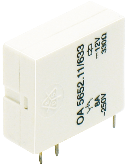 PCB relays (10)
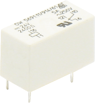 Miniature relays (6)
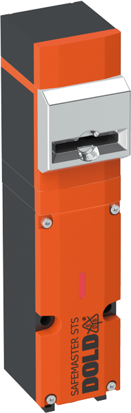 Safety switch (7)
 Guard lock (8)
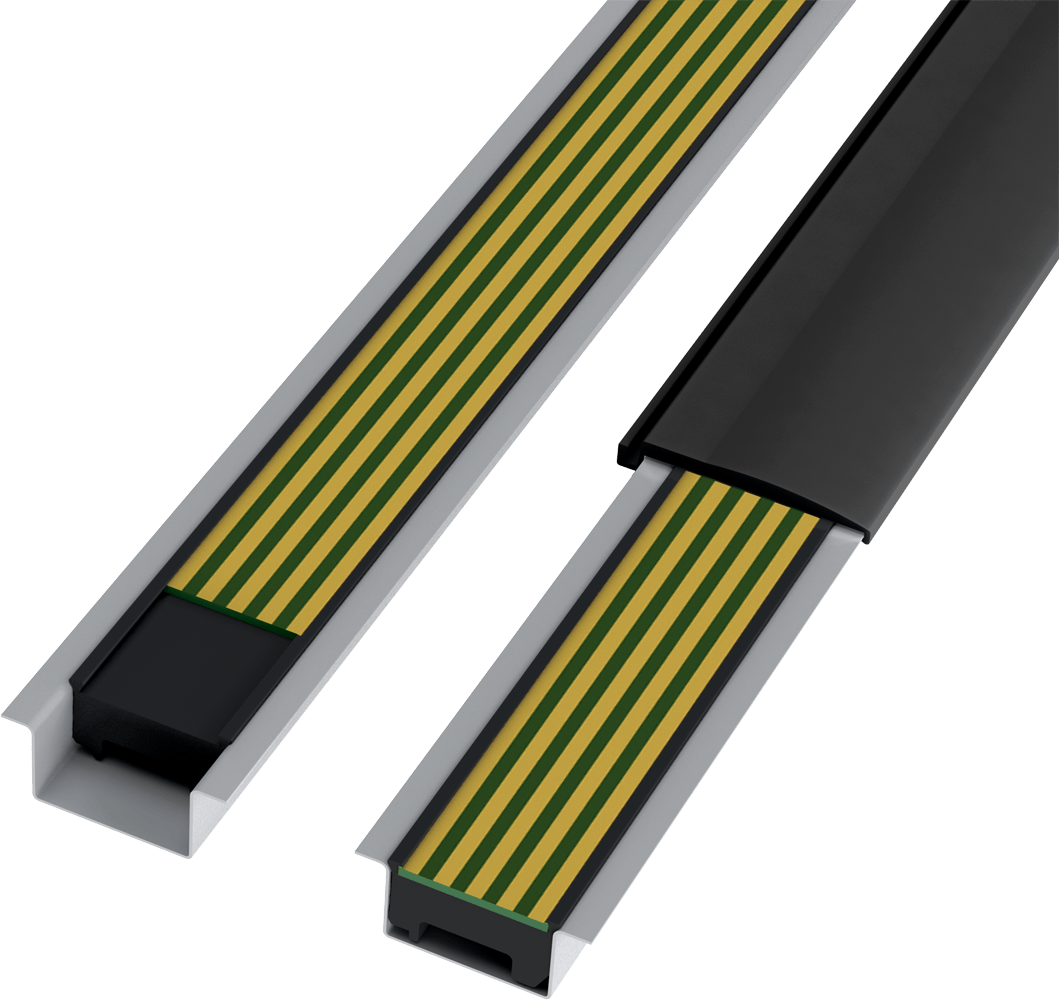 In-Rail-Bus (5)
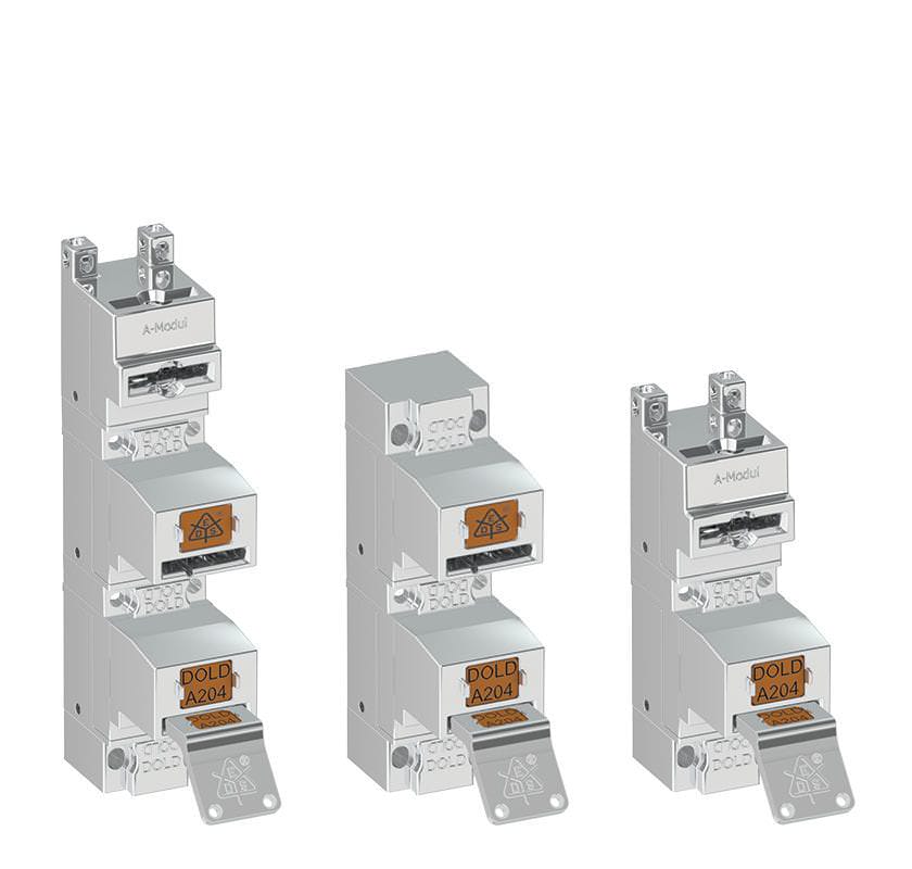 Остальная продукция (38)
- Keys (2)
- Padlock modules (4)
- Locking modules (18)
- Switch modules (6)
- Actuators (9)
- Actuator modules (7)
- Key modules (7)




О компании

Dold – Ваш надёжный партнёр в области систем контроля, управления и мониторинга.
Компания Dold одной из первых в мире начала производство распределительных устройств. Сейчас компанией управляет уже третье поколение семьи Долд. Имея более чем полувековой опыт работы, располагая самыми передовыми производственными технологиями и квалифицированным персоналом, на данный момент E. Dold & Sohne KG является ведущим европейским производителем электроники и автоматики.
Вся продукция производится в лучших традициях немецкого качества. На данный момент компания имеет свыше 400 сотрудников, многие из которых работают в ней уже более 20 лет. Именно эти люди хранят весь опыт и знания компании, что имеет гораздо более глубокий смысл, чем избитое слово «ноу-хау».
Благодаря многолетнему опыту работы, компания Dold выпускает широкий спектр продукции, уделяя особое внимание качеству производимого оборудования. Сочетание собственных разработок, технических инноваций, практического опыта и знаний позволяет удовлетворять индивидуальные требования каждого заказчика.
Все товары DOLD

(pr EN 60 947-8) and part 303
• Monitoring of
- Undervoltage 3 phase
- Phase failure
- Phase sequence
- Loss of neutral
- Phase asymmetry
- Overtemperature
- Broken wire in thermistor circuit
- Short circuit in thermistor circuit
• Without auxiliary supply
• 1 sensing input for 1 ... 6 thermistors
• LED indication
- Supply voltage
- Measuring voltage
- Temperature
• As option with manual reset on temperature fault
• 2 x 1 changeover contact
• Depth 59 mm, with terminals at the bottom for
installation systems and industrial distribution
systems according to DIN 43 880

(pr EN 60 947-8) and part 303
• Monitoring of phase failure
- Undervoltage 3-phase 3 or 4 wire
- Phase failure
- Phase sequence
- Loss of neutral
- Phase asymmetry
• Without auxiliary supply
• De-energized on trip
• LED indication
- Supply voltage
- Phase failure
• 1 or 2 changeover contacts
• Depth 59 mm, with terminals at the bottom for
installation systems and industrial distribution
systems according to DIN 43 880
• Width 35 mm
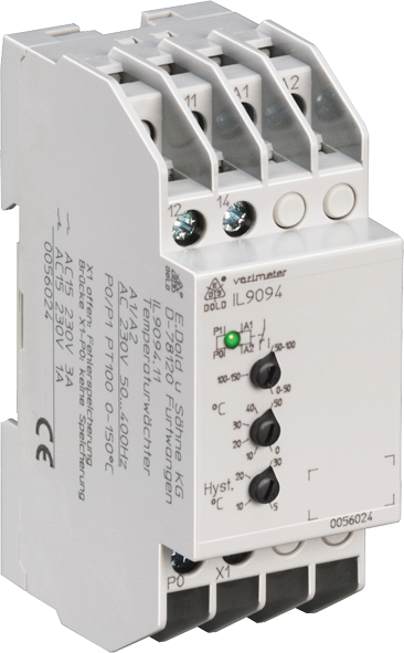
• 1 PT100 input, 2-wire connection
• 3 temperature ranges
• Adjustable response value
• Adjustable Hysteresis with wide range 3 ... 30 °C or 1 ... 15°C
• Broken wire detection in sensor circuit
• Programmable hysteresis or latching function via terminal X1
• IK 9094 no galvanic separation between measuring and Auxiliary Circuit
• Closed circuit operation
• LED indicator for operation and state of output relay
• 1 changeover contact
• As option with response value up to - 50°C, e.g. for refrigeration plants
• As option with galvanic separation between measuring and
Auxiliary Circuit
• Devices available in 2 enclosure versions:
I-model: depth 59 mm, with terminals at the bottom for
installation systems and industrial distribution systems
according to DIN 43 880
S-model: depth 98 mm, with terminals at the top for cabinets
with mounting plate and cable duct
• IK 9094, SK 9094: 17.5 mm width
IL 9094, SL 9094: 35 mm width
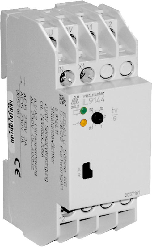
• Detection of standstill of rotating machine parts and cyclic pulses
• Detection of blocking or missing pulses
• Monitoring time adjustable between 0.1 ... 20 s (others on request)
• Energized or de-energized on trip
• For input frequency up to 5 kHz( 300000 ipm)
• Universal input, suitable for a variety of sensors
(PNP,NPN,2-wire, contact, voltage)
• Input also suitable for SKF sensor bearings
• As option for Namur sensors
• On request with manual reset
• IK 9144 and SK 9144: compact version for DC 24V auxiliary supply
• IL 9144 and SL 9144: for auxiliary supply up to AC 400V with
galvanic separation to sensor input
• LED indicators for auxiliary supply, sensor pulses and contact
position
• 1 changeover contact (2 changeover on request)
• Devices available in 2 enclosure versions:
IK/IL 9144: depth 59 mm, with terminals at the bottom for
installation systems and industrial distribution
systems according to DIN 43 880
SK/SL 9144: depth 98 mm, with terminals at the top for
cabinets with mounting plate and cable duct
• IK 9144, SK 9144: width 17.5 mm
• IL 9144, SL 9144: width 35 mm

• 3 probe connections for 2-point and 1-point level control
• Also for use as moisture detector
• High interference resistance of the Measuring Circuit,
which is isolated from the mains
• Max. wire length to the probes: 1500 m
• Large setting range: 2 ... 450 kΩ
this permits differentiation between fluid and foam
• Separately adjustable response and release time delay
0.2 ... 20 s for MIN- and MAX-level
• Programmable for:
- 2 separate controllable output relays for MIN and MAX level
- common controlled output relays for 2-point hysteresis
level control
- open circuit operation
- closed circuit operation
• Measuring Circuit for probes works with internally generated
AC voltage (approx. 30 Hz), electrolytic behaviour does not
occur in the liquid
• For auxiliary voltages of 24 ... 415 V AC or 24 V DC
• LEDs for operation and state of contact
• 2 changeover relays with 1 changeover contact each
• IL 9151 and SL 9151 with safe separation according to
IEC/EN 61 140, IEC/EN 60 947-1
• Devices available in 3 enclosure versions:
IL 9151: depth 59 mm, with terminals at the bottom for
installation systems and industrial distribution
systems according to DIN 43 880
SL 9151,
MK 9151N: depth 98 mm, with terminals at the top for
cabinets with mounting plate and cable duct
• IL/SL 9151: 35 mm width
MK 9151N: 22.5 mm width

• Monitoring of:
-- overtemperature
-- broken wire detection in sensor circuit
• 1 input for 1 to 6 PTC-resistors
• With manual reset variant /100
• Optionally with button for reset and test function
• Remote reset on A1/A2 (NC contact) or
X1/X2 (NO contact)
• Closed circuit operation
• LED indicator for
-- auxiliary supply
-- state of contact
• 2 changover contacts
• Devices available in 2 enclosure versions:
IL 9163: depth 58 mm, with terminals at the bottom for
installation systems and industrial distribution
systems according to DIN 43 880
SL 9163: depth 98 mm, with terminals at the top for cabinets
with mounting plate and cable duct
• Width 35 mm

• Monitoring of undervoltage in 3-phase system
• Also for single phase
• Without auxiliary supply
• Optionally for 3p3w systems
• LED indicator for state of output relay
• Independent of phase sequence
• 1 or 2 changeover contacts
• Optionally fixed or settable response value
• As option with phase sequence detection
• Optionally with or without N
• Optionally with off-delay t1
• Opionally with on delay t2
• Devices available in 2 enclosure versions:
I-model: depth 59 mm, with terminals at the bottom for
installation systems and industrial distribution
systems according to DIN 43 880
S-model: depth 98 mm, with terminals at the top for cabinets
with mounting plate and cable duct
• Width:
IK 9171, SK 9171: 17.5 mm
IL 9171, SL 9171: 35 mm

• Detection of
- undervoltage 1 up to 3-phase, 0.85 x UN
- phase failure
• Without auxiliary voltage
• De-energized on trip
• LED indicator for L1, L2, L3 with test key to simulate failure
• 2 changeover contacts
• Width 35 mm
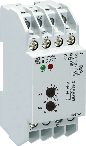
• IP 9270, SP 9270CT: 3-phase
IK 9270, SK 9270, IL 9270, SL 9270CT: single phase
• Measuring ranges from 0.1 ... 100 A
• Settable response value
• Fixed hysteresis
• Settable time delay
• De-energized on trip
• As option energized on trip
• LED indicators
• With auxiliary voltage
• Auxiliary supply and measuring input galvanic separated
• Devices available in 2 enclosure versions:
-- I-model, e.g. IK _ _ _ _, depth 61 mm
with terminals at the bottom for installation systems and
industrial distribution systems according to DIN 43 880
-- S-model, e.g. SK _ _ _ _, depth 100 mm
with terminals at the top for cabinets with mounting plate
and cable duct
• Width IK 9270, SK 9270: 17.5 mm
IL 9270, SL 9270CT: 35 mm
IP 9270, SP 9270CT: 70 mm
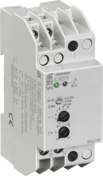
• IP 9271, SP 9271, SP 9271CT: 3-phase
IK 9271, IL 9271, SK 9271, SL 9271, SL 9271CT: single phase
• Measuring ranges from 0.1 ... 100 A
• IK 9271, SK 9271:
with 4 ranges settable by rotational switch, 1 changeover contact
• IL 9271, SL 9271:
with 5 ranges settable by rotational switch, 1 changeover contact
with 4 ranges programmable by bridges, 2 changeover contacts
• IP 9271, SP 9271: with 1 range, 2 changeover contacts
• Settable response value
• Fixed hysteresis
• Settable time delay
• De-energized on trip
• Optionally energized on trip
• LED indicators
• With auxiliary voltage
• Auxiliary supply and measuring input galvanic separated
• Devices available in 2 enclosure versions:
- I-model, e.g. IK _ _ _ _, depth 61 mm
with terminals at the bottom for installations systems
and industrial distribution systems according to DIN 43 880
- S-model, e.g. SK _ _ _ _, depth 100 mm
with terminals at the top for cabinets with mounting plate
and cable duct
• Width IK 9271, SK 9271: 17.5 mm
IL 9271, SL 9271, SL 9271CT: 35 mm
IP 9271, SP 9271, SP 9271CT: 70 mm

• IP 9277, SP 9277, SP 9277CT: 3-phase
IL 9277, SL 9277, SL 9277CT: singele phase
• Detects over- and undercurrent
• Measuring ranges from 0.1 ... 15 A
• With built in current transformer for 0.5 ... 100 A
• IL 9277, SL 9277 with 4 programmable ranges
• Settable 0.1 ... 1 IN
• Separate setting for over- and undercurrent
• Fixed hysteresis approx. 4 %
• Settable time delay
• IP 9277, SP 9277 with separate settable time delay for
over- and undercurrent
• De-energized on trip
• LED indicators for over-, under- and normal current
• Auxiliary supply and measuring input galvanic separated
• IL 9277, SL 9277 with one output relay for over- and
undercurrent
• IP 9277, SP 9277 with separate output relays for over- and
undercurrent
• Optionally energized on trip
• Devices available in 2 enclosure versions:
-- I-model, e.g. IL _ _ _ _, depth 61 mm
with terminals at the bottom for installations systems
and industrial distribution systems according to DIN 43 880
-- S-model, e.g. SL _ _ _ _, depth 100 mm
with terminals at the top for cabinets with mounting plate
and cable duct
• DIN rail or screw mounting
• Width IL 9277, SL 9277, SL 9277CT: 35 mm
IP 9277, SP 9277, SP 9277CT: 70 mm
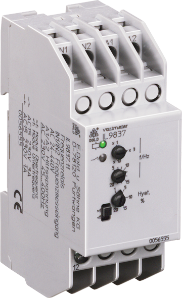
• Overfrequency or underfrequency monitoring of AC voltages
• Adjustable response value fmin. or fmax 5 ... 200 Hz or 15 ... 600 Hz
• Adjustable hysteresis
• Large voltage range of the measuring input (nominal voltage
AC 24 ... 440 V)
• De-energized on trip
• LED indication for auxiliary voltage, measuring voltage and contact
position
• 1 changeover contact
• As option for frequency inverters with a range of 1 … 300 Hz
• 2 changeover contacts available on request
• As option adjustable start-up delay available
• Energized on trip function available on request
• Devices available in 2 enclosure versions:
IL 9837: depth 58 mm, with terminals at the bottom for
installation systems and industrial distribution
systems according to DIN 43 880
SL 9837: depth 98 mm, with terminals at the top for cabinets
with mounting plate and cable duct
• 35 mm width

• Operation as master
- Operation as slave
- Transfer rate up to 1 Mb/s
- Interface according to DS301 version 3.0
• IN 5504 locally extendable with digital and analoge in- / output
modules
• 2 digital inputs for DC 24 V
• 2 relay outputs
• LED indicators
• Standard programming software CODESYS® under Windows
according to IEC/EN 61131-3:
- Instruction set
- Ladder diagram
- Function block diagram
- Sequential function chart
- Structured text (similar to Pascal)
• 128 KB Flash memory for user program
• 128 KB RAM for user data
• 16 KB battery buffered RAM for no-voltage safe data
• Battery buffered real time clock
• Monitoring contact for RUN status of the PLC
• IL 5504: 35 mm width
IN 5504: 52.5 mm width
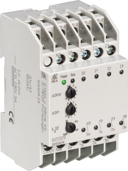
• CANopen interface according to DS 301 version 3.0, DS 401
• 4 digital inputs for DC 24 V
• 4 relay outputs
• LED indicators
• 52.5 mm width

• For rooms used for medical purposes
according to IEC 60364-7-710, DIN VDE 0100-710
• For three-phase and A.C. power systems with 0 … 500 V
and 10 … 1000 Hz (IT power systems)
• Adjustable alarm value for ground fault RAL of 50 … 500 kΩ
• Measuring circuit with broken wire protection
• As option, programmable for storing or non-storing of errors
• With reset and test button
• Additional external reset and test buttons can be connected
• LED indicators for operation, insulation fault, and interruption of
Measuring circuit
• 2 changeover contacts
• With LED chain for indication of the current insulation status
• IP 5880/711 for connection of the test and display panel UP 5862
• 52.5 mm width
- Performance Level (PL) c and category 2 to EN ISO 13849-1: 2008
- SIL Claimed Level (SIL CL) 2 to IEC/EN 62061
- Safety Integrity Level (SIL) 2 to IEC/EN 61508
- Category 2 to EN 954-1
• BA 7924.21/002 und BA 7924.21/003
- Performance Level (PL) d and category 3 to EN ISO 13849-1: 2008
- SIL Claimed Level (SIL CL) 2 nach IEC/EN 62061
- Safety Integrity Level (SIL) 2 to IEC/EN 61508
- Category 3 to EN 954-1
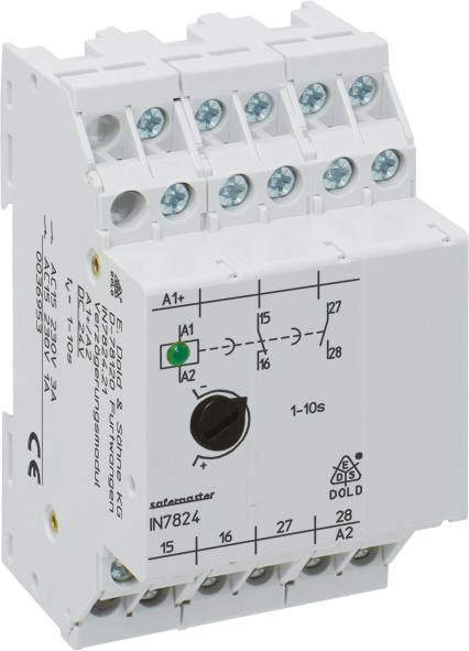
• Release delay
• Without auxiliary voltage
• Output: 1 NC, 1 NO contacts, forcibly guided
• Operating state display
• Optionally with adjustable or fixed time delay up to 30 s
• Optionally with redundant timing circuit
• Optionally with 1 or 2 separate timing circuits
• Optionally also in housing for distribution board
• Width 45 mm, 35 mm or 52.5 mm
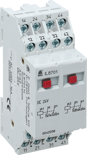
• Optionally contacts with up to a maximum 4 changeover contacts
• High thermal current Ith
• Pushbutton for manual actuation of the contact
• Operating position display
• Optionally without manual actuation and an operating position display
• Optionally for 2-wire initiator activation
• Optionally for switching low loads
• Optionally for switching lamps with parallel compensation (e.g. HQ lamps)
• Optionally for switching large inductive direct current loads
• Optionally with a recovery diode (only DC devices)
• Optionally with reliable release voltage of AC 120 V
• IK 8701: width 17.5 mm
IL 8701: width 35 mm
IN 8701: width 52.5 mm
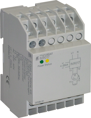
• for permanent power up to 300 W
• Interference suppression limit value class B
• LED indication
• Devices available in 3 versions:
IN 9017/100: with current interface 4 ... 20 mA
and broken wire detection
IN 9017/200: with voltage interface 0 ... 10 V
IN 9017/211: with voltage interface 0 ... 10 V,
Umin adjustable, control input for
max. output current
• Width: 53 mm
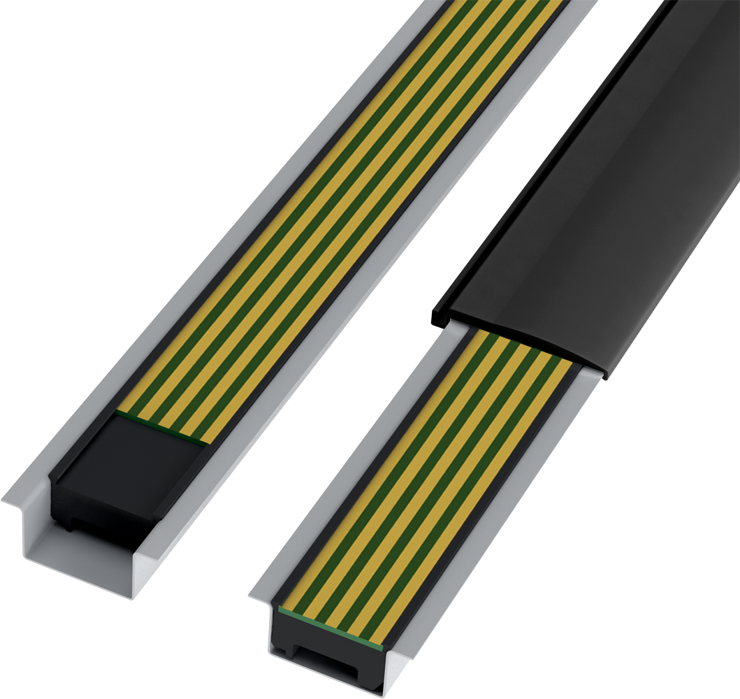
• High current (5 A per pcb-rail)
• Quick and easy mounting in the DIN-rail
• Contour and layout of the bus pcb
can be adapted according to customers'
requirements e.g. defined by the customer
• Designed for standard DIN-rail
dimensions
• Optional coding of the bus system to
prevent incorrect assembly
• Large stand-off to DIN-rail floor allows
the mounting of SMD components on
the bus pcb underside
• The carrier profile is securely fixed by safety
caps (left and right) on the DIN-rail
• Pcb rail "breaks" are possible, e.g. for
operation of bus signals inside
instruments
Запросите коммерческое предложение






 Ответ от производителя может занять до 5 дней и более.